Performance Verification
2500A Series Operation Manual, 34172 Revision C, March 2008
4.3.3.2 Frequency Modulation Tests
The following procedures test Frequency Modulation Accuracy and Maximum Deviation at frequencies
within the 4 to 8 GHz band. The procedures identify a Bessel null for each of the test frequencies in both
narrow and wide mode FM.
4.3.3.2.1 Equipment Required
• Function Generator
4.3.3.2.2 Test Setup
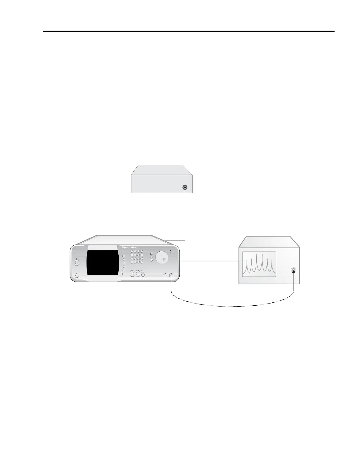
Figure 4-6: FM Deviation Bandwidth and Accuracy Setup
4.3.3.2.3 Procedure - Narrow Mode FM Maximum Deviation Test
1. Connect the test equipment and UUT as shown in Figure 4-6.
2. Set the Function Generator to the following settings:
Waveform: Sine wave
Rate: 41.06 kHz
Output: 2 Vp-p into 50Ω
3. Set the Spectrum Analyzer to the following settings:
MICROWAVE SYNTHESIZER (UUT)
RF IN
Spectrum Analyzer
RF OUT
2500A Microwave Synthesizer
OUTPUT
Function Generator
Timebase
IN
OUT