Chapter 2: Front Panel Operation
24 2500A Series Operation Manual, 34172 Revision C, March 2008
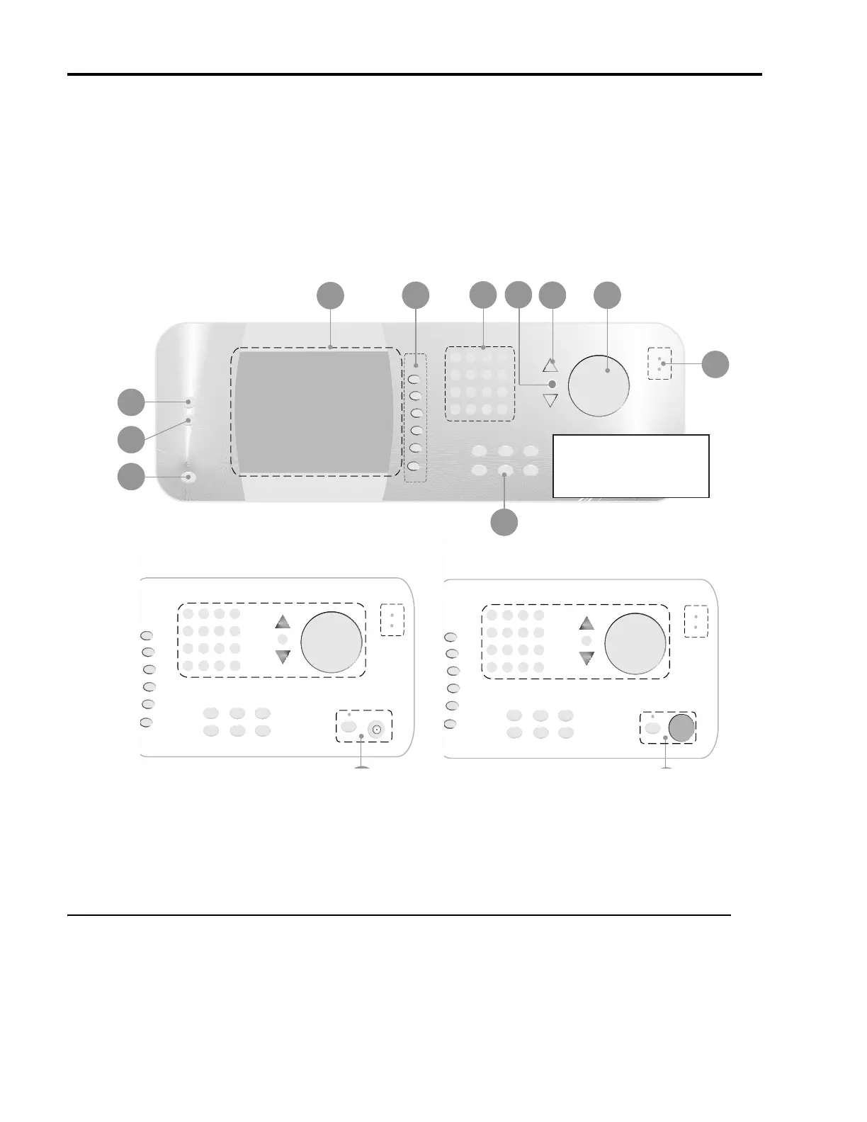
Figure 2-1: 2500A Front Panel with Callouts
2.2.1 Front Panel Description
Power
The main power switch for the 2500A, which is used to set the power either to on or standby. A blue
indicator indicates that main power button is blue, an amber indicator indicates that the main power is off
but power is applied to the internal timebase oscillator.
1
3
10
2
4
8
Microwave Synthesizers
Bottom Sectional Differential
See A for 2500A Series
See B for 2500AS Series
12
Front Panel Layout of 2500 Series Microwave Synthesizers
6
9
5
7