Chapter 4: Specifications & Performance Verification
114 2500A Series Operation Manual, 34172 Revision C, March 2008
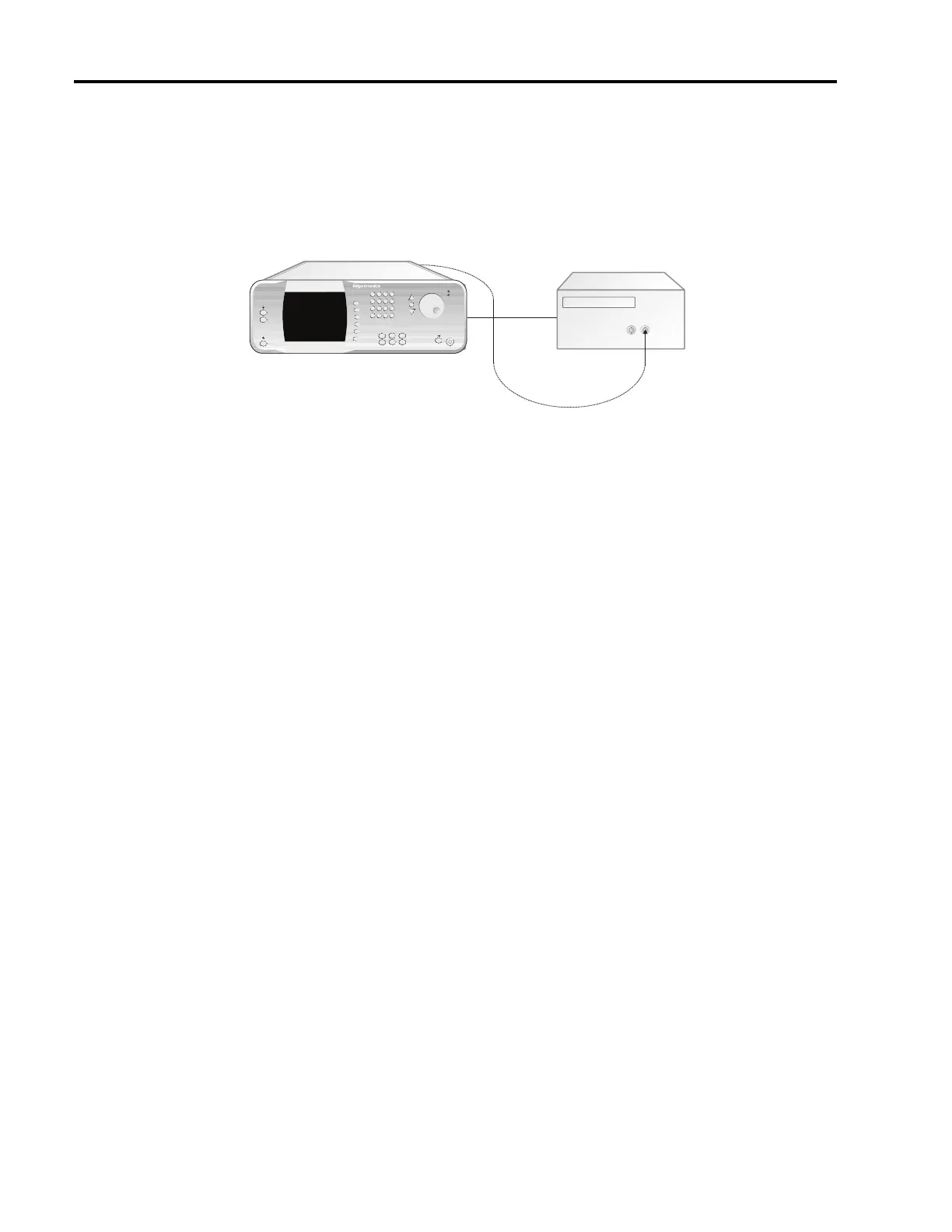
Figure 4-10: Internal Modulation Generator Tests
4.3.3.4 Internal Modulation Generator Tests
The following verification tests are for all models that do not have option 17.
4.3.3.4.1 AM Frequency Accuracy Test
1. Connect the test equipment and UUT as shown in Figure 4-10. Connect a BNC cable from the AM
Out connector to the Band 1, BNC connector of the frequency counter
2. Set the CW frequency of the 2500A to 6 GHz.
3. Press the AM button to activate the AM Menu. If AM Menu 2 is not displayed, press the AM X/3
softkey until AM Menu 2 is displayed.
4. Press the AM softkey and the Step Up button to activate the Internal AM Modulation Generator.
The AM indicator will appear in the upper left corner of the display.
5. Press the Rate softkey and enter the first value on Datasheet 11. Measure and record the reading of
the frequency counter.
6. Repeat Step 5 for the remaining data points on the datasheet.
4.3.3.4.2 FM Frequency Accuracy Test
1. Connect the test equipment and UUT as shown in Figure 4-10. Connect a BNC cable from the FM
Out connector to the Band 1, BNC connector of the frequency counter.
2. Set the CW frequency of the 2500A to 6 GHz.
IN
Input
<1 GHz
Frequency Counter
OUT
MICROWAVE SYNTHESIZER (UUT)
Timebase
(Series 2500A Series Illustrated)
2500A Microwave Synthesizer
AM, FM, or PM Out