2500A Chapter 3: Remote Operation
70 2500A Series Operation Manual, 34172 Revision C, March 2008
3.1.2 Computer Interfaces
The following computer interfaces are supported by the 2500A.
GPIB. The IEEE 488.2 interface connection (24-pin) between the 2500A Series and host computer
equipment for remote operation over GPIB is located on the rear of the unit. The connector pin assign-
ments are listed in Table 3-1 (pin assignments are the same for all 2500A Series models).
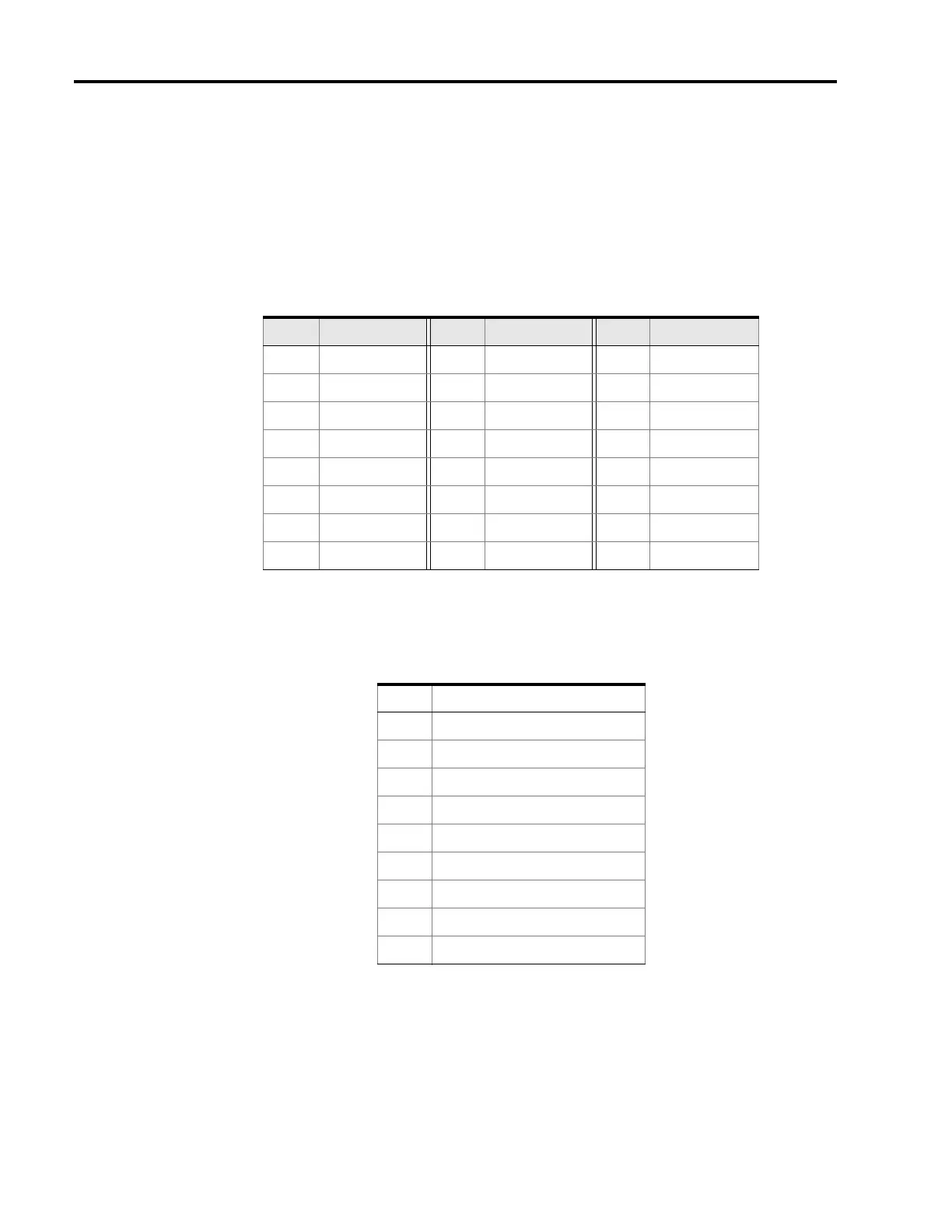
Table 3-1: GPIB Connector Pin Assignments
RS-232. This 9 pin connector interfaces communications equipment using RS-232 format. See Table 3-
2 for the connector pin assignments (pin assignments are the same for all 2500A Series models). Table
3-3 contains the 2500A Series serial interface communication settings.
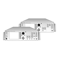
Table 3-2: RS-232 Connector Pin Assignments
Pin Signal Pin Signal Pin Signal
1D101 9IFC 17REN
2 D102 10 SRQ 18 GND (6)
3 D103 11 ATN 19 GND (7)
4 D104 12 Shield 20 GND (8)
5 E0I 13 D105 21 GND (9)
6 DAV 14 D106 22 GND (10)
7 NRFD 15 D107 23 GND (11)
8 NDAC 16 D108 24 GND Logic
Pin Function
1 Protective Ground
2 Transmitted Data
3 Received Data
4Not Used
5Not Used
6Not Used
7Not Used
8Not Used
9Not Used