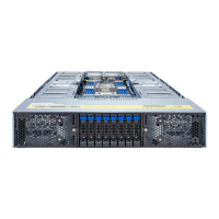
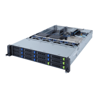
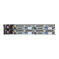
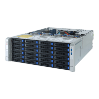
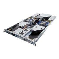
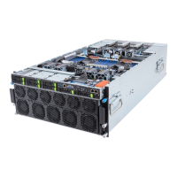
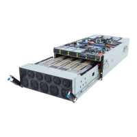
- 13 - Hardware Installation
Front Panel
LED/Buttons
(R152-Z30)
2 x USB 3.0
1 x Power button with LED
1 x ID button with LED
1 x NMI button
1 x Reset button
2 x LAN activity LEDs
1 x HDD activity LED
1 x System status LED
(R152-Z31)
(R152-Z32)
1 x USB 3.0
1 x Power button with LED
1 x ID button with LED
1 x NMI button
1 x Reset button
2 x LAN activity LEDs
1 x HDD activity LED
1 x System status LED
Rear Panel I/O 3 x USB 3.0
1 x VGA
2 x RJ45
1 x MLAN
1 x ID button with LED
Backplane I/O
(R152-Z30)
SATA(6Gb/s)
(R152-Z31)
(R152-Z32)
SAS(12Gb/s) / SATA(6Gb/s)/ NVMe(8Gb/s)
TPM 1 x TPM header with SPI interface
Optional TPM2.0 kit: CTM010
System
Management
Aspeed® AST2500 management controller
Avocent® MergePoint IPMI 2.0 web interface:
Network settings
Network security settings
Hardware information
Users control
Services settings
IPMI settings
Sessions control
LDAP settings
Power control
Fan proles
Voltages, fans and temperatures monitoring
System event log
Events management (platform events, trap settings, email settings)
Serial Over LAN
vKVM & vMedia (HTML5)
 Loading...
