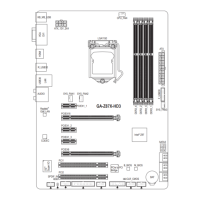
1-8 OnboardButtons,Switches,andLEDs
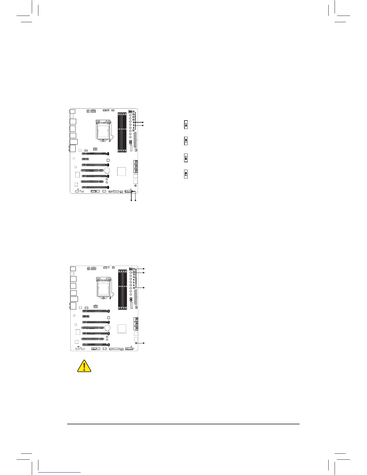
BIOSSwitchesandBIOSLEDIndicators
The BIOS switch (BIOS_SW) allows users to easily select a different BIOS for boot up or overclocking,
helping to reduce BIOS failure during overclocking. The SB switch allows enabling or disabling of the Dual
BIOS function. The LED indicator (MBIOS_LED/BBIOS_LED) shows which BIOS is active.
BIOS Switches:
BIOS LED Indicators:
DIP
1 23
4
2: Backup BIOS (Boot from the backup BIOS)
1: Main BIOS (Boot from the main BIOS)
2: Single BIOS
1: Dual BIOS
BIOS_SW
SB
MBIOS_LED
BBIOS_LED
DIP
1 23
4
QuickButtons
This motherboard has four quick buttons: Power, Reset, Clear CMOS, and Clear Battery. The power button and
reset button allow users to quickly turn on/off or reset the computer in an open-case environment when they
want to change hardware components or conduct hardware testing. Use the clear CMOS button to clear the
BIOS conguration and reset the CMOS values to factory defaults when needed. The Clear Battery button has
the same function as removing the battery from the motherboard.
PW_SW:Power button
RST_SW:Reset button
CMOS_SW:Clear CMOS Button
CBAT_SW:Clear Battery Button
• Always turn off your computer and unplug the power cord from the power outlet before using
the clear CMOS button.
• Always turn off the power of the power supply before using the clear battery button. After pressing
this button, make sure to wait for ve minutes before you turn on the computer.
• Do not use the clear CMOS or clear battery button when the system is on, or the system may
shut down and data loss or damage may occur.
• After system restart, go to BIOS Setup to load factory defaults (select Load Optimized Defaults) or
manually congure the BIOS settings (refer to Chapter 2, "BIOS Setup," for BIOS congurations).
CBAT_SW
CMOS_SW
PW_SW
RST_SW
MBIOS_LED (The main BIOS is active)
BBIOS_LED (The backup BIOS is active)
BIOS_SW
SB
1
2
 Loading...