EasyManuals Logo

Gigabyte GA-Z87X-OC User Manual

Gigabyte GA-Z87X-OC
112 pages
To Next Page IconTo Next Page
To Previous Page IconTo Previous Page
Page #28 background imageLoading...
Page #28 background image
- 28 -
Hardware Installation
Be sure to connect fan cables to the fan headers to prevent your CPU and system from
overheating. Overheating may result in damage to the CPU or the system may hang.
These fan headers are not conguration jumper blocks. Do not place a jumper cap on the headers.
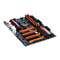
4/5)CPU_FAN/SYS_FAN1/2/3/4/5/6(FanHeaders)
The motherboard has a 4-pin CPU fan header (CPU_FAN), four 4-pin (SYS_FAN1/SYS_FAN2/SYS_FAN3/
SYS_FAN4) and two 3-pin (SYS_FAN5/SYS_FAN6) system fan headers. Most fan headers possess a
foolproof insertion design. When connecting a fan cable, be sure to connect it in the correct orientation
(the black connector wire is the ground wire). The speed control function requires the use of a fan with
fan speed control design. For optimum heat dissipation, it is recommended that a system fan be installed
inside the chassis.
CPU_FAN:
Pin No. Denition
1 GND
2 +12V
3 Sense
4 Speed Control
CPU_FAN
DEBUG
PORT
G.QBOFM
1
DEBUG
PORT
G.QBOFM
1
3) OC_PEG(PCIePowerConnector)
The power connector provides auxiliary power to the onboard PCI Express x16 slots. When two or more
graphics cards are installed, we recommend that you connect the 2x3 power cable from the power supply
to this connector to ensure system stability.
Pin No. Denition
1 +12V
2 +12V
3 +12V
4 GND
5 GND
6 GND
F_USB30
F_AUDIO(H)
DB_PORT
F_PANEL(NH) F_PANEL
(H61M-D2)
ACPI_CPT
(GA-IVB)
BIOS_PH
(GA-IVB)
SMB_CPT
(GA-IVB)
CLR_CMOS
CI
DIS_ME
GP15_CPT
(GA-IVB)
XDP_CPU
XDP_PCH
(GA-IVB)
TPM
w/housing
Voltage measurement module(X58A-OC)
PCIe power connector (SATA)(X58A-OC)
DIP
123
DIP
123
DIP
123
DIP
123
1
1
1
1
BIOS Switcher (X58A-OC)
PWM Switch (X58A-OC)
M_SATA
PWM Switch (SW1)(X79-UD7)
DIP
1 2 3 4 5
Voltage measurement points(G1.Sniper 3)
BIOS Switcher (SW4)
PCIe Control (Z87X-UP7)
DIP
1 2 3
4
DIP
1 2 3 4
DIP
1 2 3
4
DIP
1 2 3 4
ATX_12V_2X3
F_USB3 (Front Panel)
1
SYS_FAN1/2/3/4:
Pin No. Denition
1 GND
2 +12V /Speed Control
3 Sense
4 VCC
SYS_FAN5/6:
Pin No. Denition
1 GND
2 +12V
3 NC
SYS_FAN1/2/3/4
DIP
1 23
4
DIP
1 23
4
SYS_FAN6
1
SYS_FAN5
1
4
3
6

Table of Contents

Questions and Answers:

Question and Answer IconNeed help?

Do you have a question about the Gigabyte GA-Z87X-OC and is the answer not in the manual?

Gigabyte GA-Z87X-OC Specifications

General IconGeneral
ECCNo
Non-ECCYes
Memory voltage1.5 V
Memory channelsDual-channel
Memory slots typeDIMM
Number of memory slots4
Supported memory typesDDR3-SDRAM
Maximum internal memory32 GB
Supported memory clock speeds1333, 1600, 3000 MHz
Processor manufacturerIntel
Compatible processor seriesIntel Celeron, Intel Pentium
Supported processor socketsLGA 1150 (Socket H3)
Maximum number of SMP processors1
Number of SATA III connectors6
Number of Parallel ATA connectors0
USB 3.2 Gen 1 (3.1 Gen 1) connectors2
HDMI version1.4a
USB 2.0 ports quantityUSB 2.0 ports have a data transmission speed of 480 Mbps, and are backwards compatible with USB 1.1 ports. You can connect all kinds of peripheral devices to them.
Audio chipRealtek ALC892
Cooling typePassive
Component forPC
Motherboard chipsetIntel® Z87
PC health monitoringCPU, FAN, Temperature
Audio output channels7.1 channels
Motherboard form factorATX
RAID levels0, 1, 5, 10
Supported storage drive interfacesSATA, SATA II, SATA III
Graphics cardHD Graphics
Maximum resolution4096 x 2160 pixels
Parallel processing technology support2-Way CrossFireX, 2-Way SLI, 3-Way CrossFireX, 4-Way CrossFireX
PCI Express slots version2.0, 3.0
PCI Express configurations1x8, 1x16, 2x4
Cables includedSATA
Ethernet interface typeGigabit Ethernet
BIOS typeEFI AMI
ACPI version2.0a
BIOS memory size16 Mbit
Weight and Dimensions IconWeight and Dimensions
Depth244 mm
Width305 mm

Related product manuals