THE ADVANCED SWITCHING SYSTEM
THE GIGRIG G3 USER MANUAL
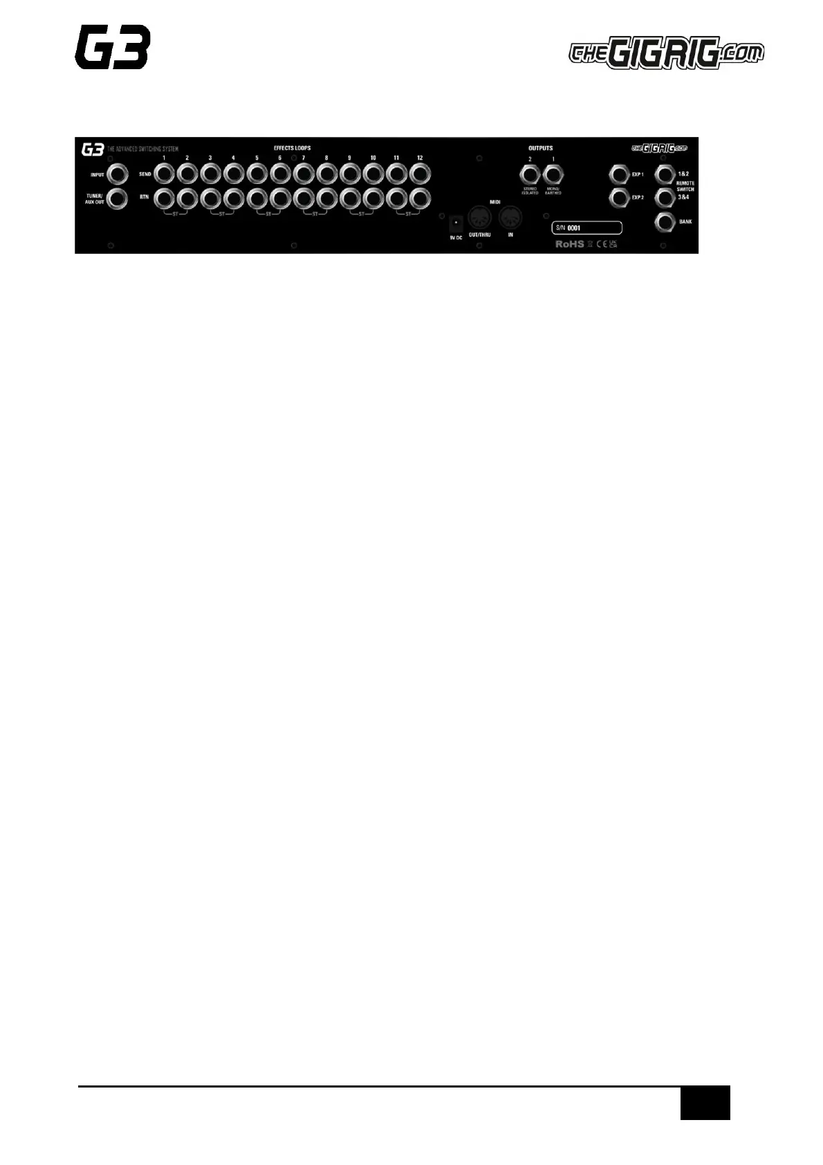
3. CONNECTIONS
All of G3’s connections are made via the back panel.
3.1. INPUT - Connect your guitar here. For stereo input use a TRS cable.
3.2. TUNER/ AUX OUT – Sends your input signal to the tuner so you can tune silently on stage. You can also use
this connection as a TRS loop. (Tip = Send, Ring = Return). This loop is hard wired and cannot be moved in the
signal path. It sits BEFORE the pre-gain circuit.
3.3. EFFECTS LOOPS - There are 12 mono effects loops in G3 that can be configured in various different ways.
For example, you can pair them for stereo effects, connect them to your amplifier’s effects loop (four cable
method), connect your volume pedal, re-order the effects loops or create a wet/dry set up. Loops can also be
configured in parallel or sent to different outputs.
3.4. OUTPUTS - These two outputs connect to our amplifiers or audio interface.
IMPORTANT! OUTPUT 1 is your EARTH/GROUND and MUST be connected. OUTPUT 2 is isolated using our
High-Def Isolation technology to prevent earth loops when using two amps. This is where you connect your
second amp. If you are only using one amp, you MUST connect to Output 1.
3.5. REMOTE SWITCHES - The G3 features four remote switches configured into two TRS remote switch
sockets, which are programmable via the push buttons on G3’s centre panel. These can be used to change
channels in your amplifier, Tap Tempo control, to control a Remote Loopy – in fact, they can be used for
anything that uses isolated latching or momentary switches.
3.6. BANK REMOTE SWITCH - Connect a momentary switch into the BANK input and you will be able to control
your G3 banks remotely.
To BANK UP, tap the momentary switch.
To BANK DOWN, hold the switch down and you will see the bank numbers start to descend.
PLEASE NOTE – a latching switch will NOT work here.
3.7. MIDI IN & OUT - This is where you connect your MIDI IN and MIDI OUT cables from G3 to control your MIDI
effects. The connection is a standard five pin din cable.
3.8. POWER (9V DC) - G3 uses a standard centre 9V DC input connection. G3 operates around 850 mA, so it is
important that your power supply can provide sufficient current. The GigRig Generator Power Supply is included
with your G3 so you can add elements of our Modular Power Supply to enable you to power G3 and your entire
board.
3.9. EXPRESSION PEDALS (EXP1 & EXP2) - G3 has two expression pedal ports that use a TRS connector. These
can be used to send MIDI CC information, as well as being able to control G3’s PRE GAIN and POST GAIN