Connectors
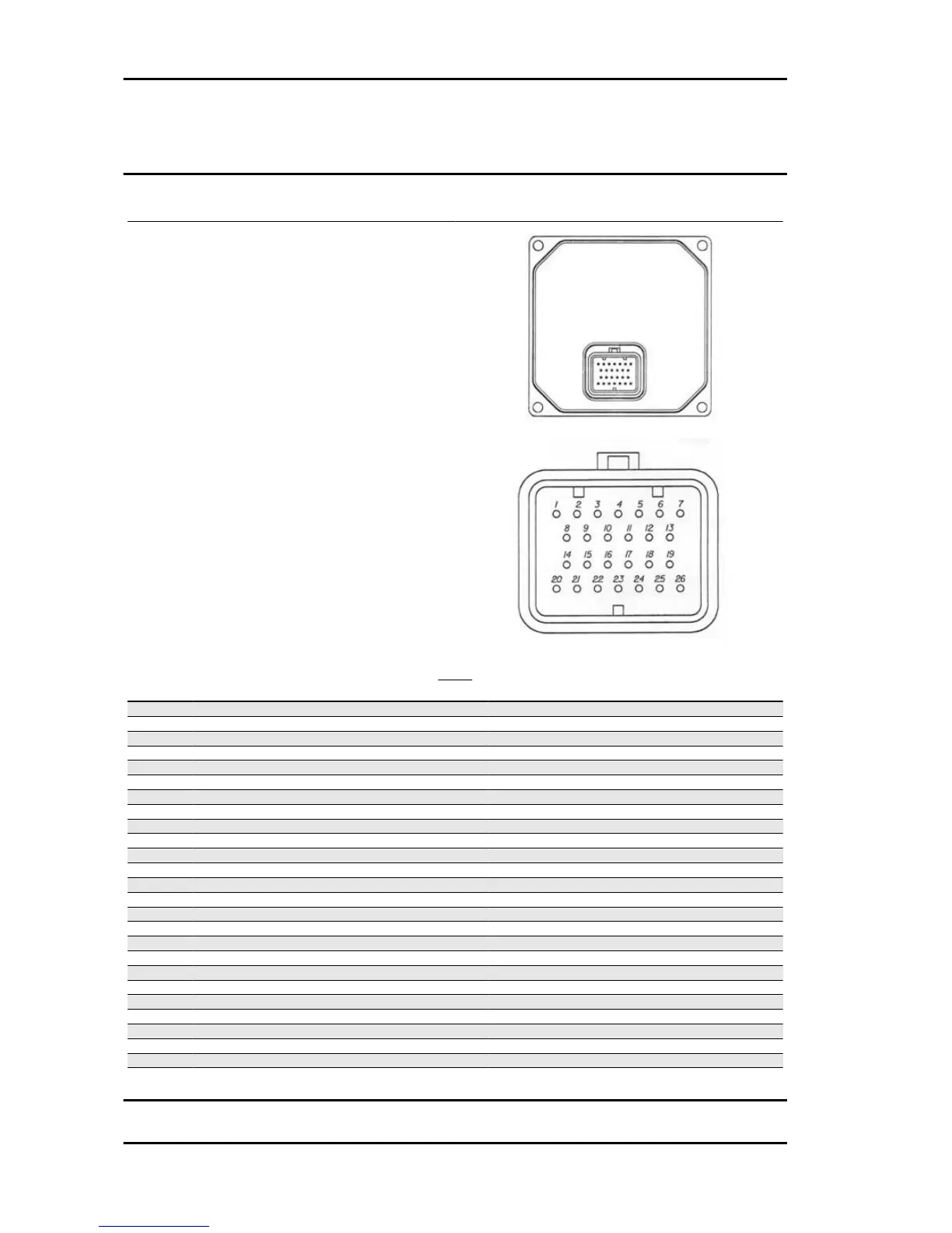
ECU
Layout of the system-side connectors and the con-
nectors on the electronic control unit.
ECU
Specification
Desc./Quantity
1 Throttle potentiometer power supply +5 V
2 Oxygen sensor (-)
3 Rpm indicator / consumption counter
4 Engine temperature (+)
5 86 electric fan remote control switch
6 Stepper motor Stepper motor
7 Engine rpm sensor
8 Oxygen sensor (+)
9 EMS diagnostic connector
10 EMS diagnostic connector
11 Throttle potentiometer signal
12 Engine rpm sensor
13 Injector control (negative)
14 Stepper motor Stepper motor
15 Injection telltale light (-)
16 Decoder (serial) Overturn sensor
17 Battery powered (+)
18 Air temperature sensor (+)
19 Fuel pump (-)
20 H.V. coil (negative control)
21 Stepper motor Stepper motor
22 Sensor power supply (-)
23 Control unit negative
24 Stepper motor Stepper motor
25 Turn indicator control device
26 Continuous power supply (positive)
Electrical system Nexus 500 euro 3
ELE SYS - 72