T X 4 5 0 0 I N S T R U C T I O N M A N U A L PA G E 2 3
Lift microphone cover
lead. Mount the socket on a convenient location and
feed the plug through the dashboard to the DIN cavity.
The rear microphone cover hinges from the top. Simply
lift the cover from the bottom. The cover will remain
connected to the chassis.
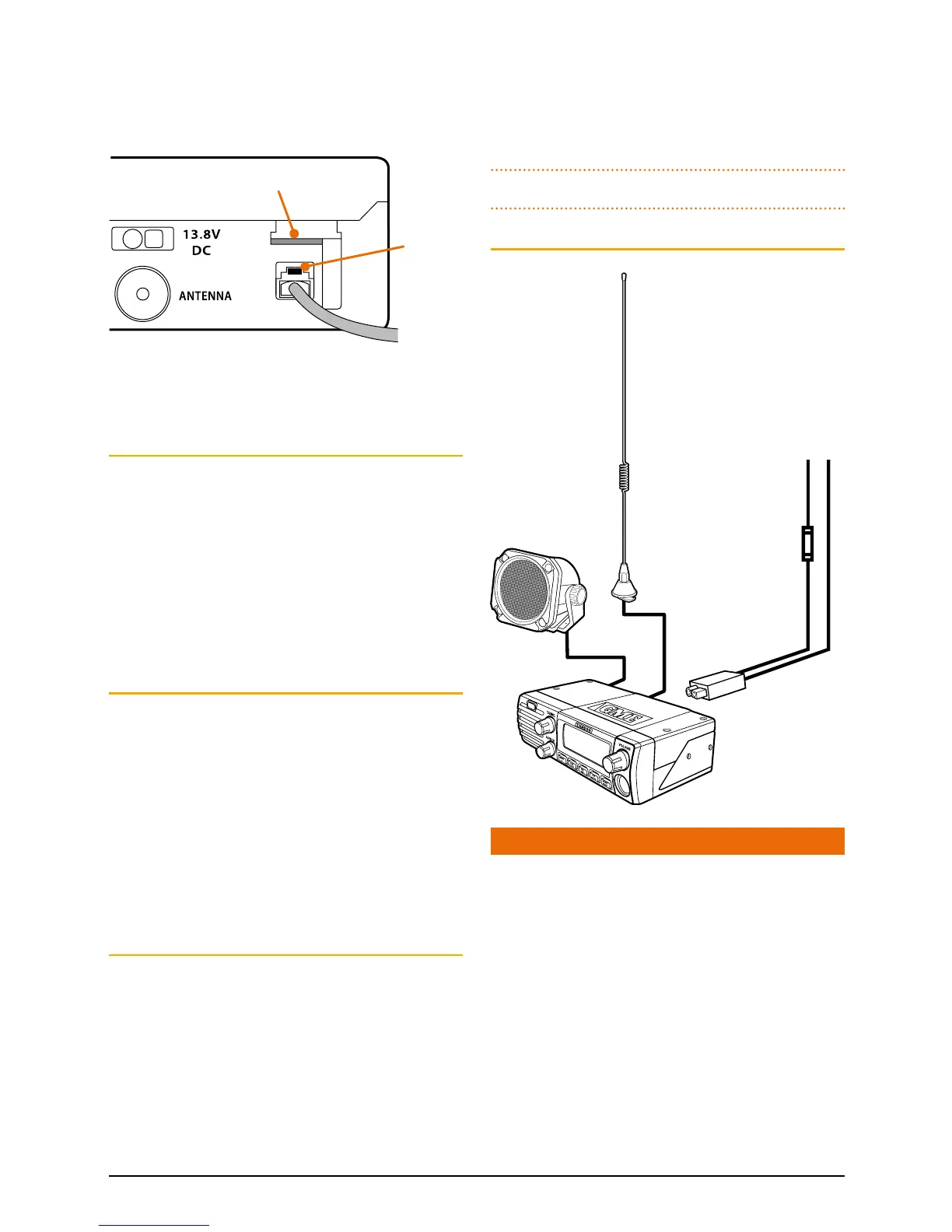
Position the microphone plug so the plastic tab faces
upwards then press the plug into the socket until
it ‘clicks’.
Removing the microphone
For front panel connections, first squeeze the grommet
to disengage it from the slot then slide it along the
microphone cord.
For both connections, squeeze the microphone plug’s
plastic tab towards the plug to unlock it while gently
pulling on the microphone cable. The plug should
release from the socket. If the plug does not come out
easily, the tab has not been release fully – squeeze the
tab again.
ANTENNA INSTALLATION
It is essential to install a good quality, high efficiency,
477 MHz antenna. A poor quality antenna or one not
designed for the specific frequency band will give very
poor performance.
GME have a huge range of suitable 477 MHz antennas
to suit most installations and applications. We
recommend you contact your local retailer for advice.
After mounting the antenna, feed the antenna cable
to the DIN cavity in the vehicles console or dashboard
before mounting the radio.
High voltage detection
The radio has a built-in, high voltage detection system
to warn you if an overvoltage situation occurs. If the
power supply voltage exceeds 18 volts DC, the channel
display will flash ‘hi dc’ for 5 seconds when the unit is
first turned on, or at the time the voltage exceeds 18
volts. In addition, when transmitting, the TX indicator
will flash and the transmitter will select low
output power.
If the overvoltage warning appears you should switch
your radio OFF and disconnect it from the power
source, before locating the cause of the trouble.
Once the ‘High Voltage’ warning has been triggered,
and you have fixed the source of the problem, you will
need to switch the radio OFF then ON again to reset it.
Note: The power source should never exceed 25 volts.
WIRING
NOISE SUPPRESSION
The inherent design of FM transceivers results in a high
level of resistance to ignition and electrical interference.
However in some installations it may be necessary
to take additional steps to help reduce or eliminate
noise interference. During installation, try to route the
DC battery leads, the antenna lead or any accessory
wires away from the engine compartment, ignition
or alternator wiring. If the noise continues, it may be
necessary to fit a suppression kit in which case we
recommend you consult an auto electrician for advice
specific to your installation.
Higher frequency electrical interference cause by
electric motors can be suppressed directly at the motor
terminals.
Plastic
tab
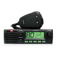
Antenna
12 V DC
RED +
Fuse
Coax cable
DC connector
Extension speaker
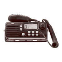
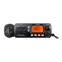
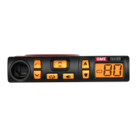
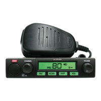
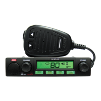
TX4500
C