47
5- 2 C utte r Insta lla tio n
C utte r pa rts intro duc tio n
C utte r Mo dule Insta lla tio n Ste ps:
(Fo llo w ing Ste p s must b e und e r p rinte r p o we r o ff c o nd itio n)
No te
* Be fo re c utte r insta lla tio n, ma ke sure the p rinte r is und e r p o we r o ff c o nd itio n o r the p o we r c o rd is
no t p lug g e d !
** The line rle ss me d ia is no t a va ila b le sup p o rte d .
*** The ma xim um c utting wid th is 230 m m,the minim um c utting he ig ht is 30 mm a b o ve . (If o ve r the
ra ng e the n it’ s no t und e r w a rra nty c o nd itio n)
**** Sug g e ste d Sto p Po sitio n fo r C utte r is (^E) 29~30。
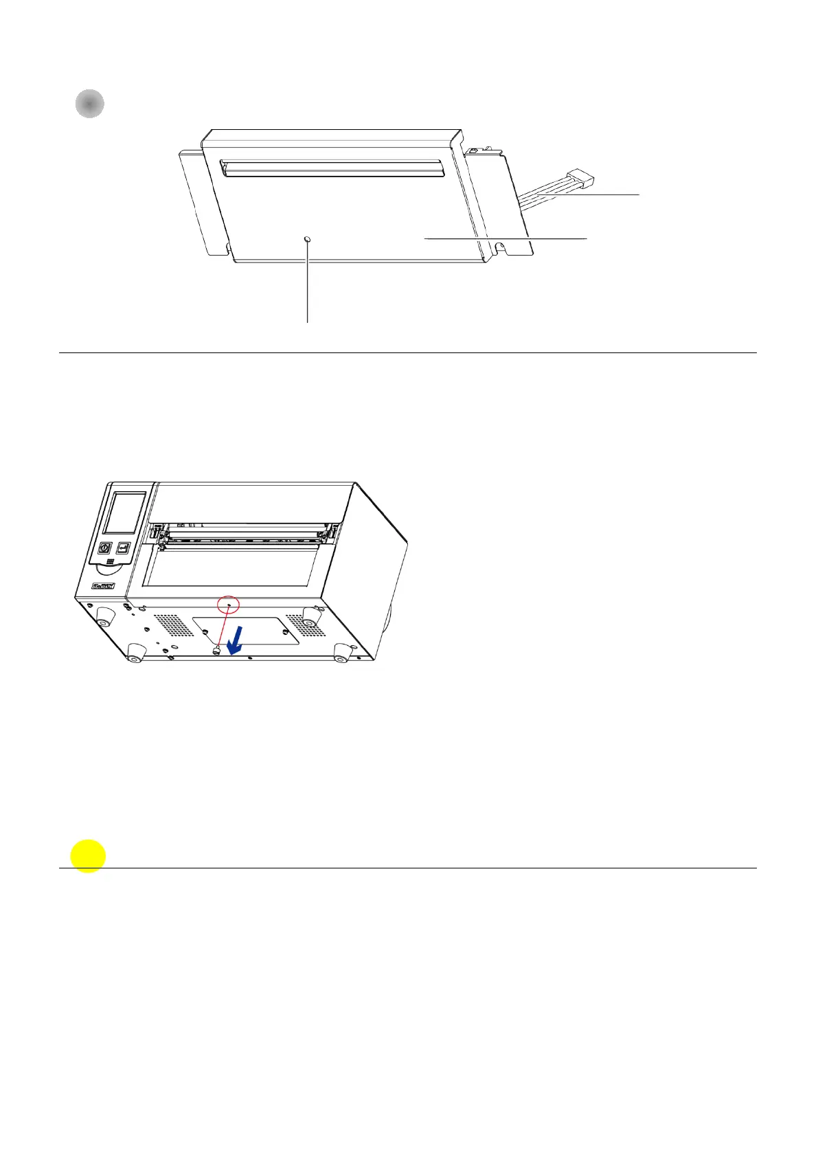
Front cover
Cutter cable
Front cover
Step 1. Disassemble the bottom case screws (Marked in Red circle)