OPERATOR Book No.: 95-0014-0000/A
HANDBOOK Issue: 06
Page 10 of 30
7.2 HS100, HS100-SG, HS103, HS150, HS150-SG, HS150V & HS150V-
SG pumps
NOTE! The HS100NC & HS150NC pumps differ only in volute, impeller and associated parts. Therefore these
dismantling and reassembly instructions can be followed in principle, but refer to section 7.5 for detail differences.
Note that dismantling and reassembly procedures refer to the item numbers in the illustrations and are correct for a
directly corresponding build. However because of the number of possible build configurations some interpretation of the
diagrams will be necessary for other pump variants. Some additional illustrations have been included to aid in this
purpose.
7.2.1 Dismantling
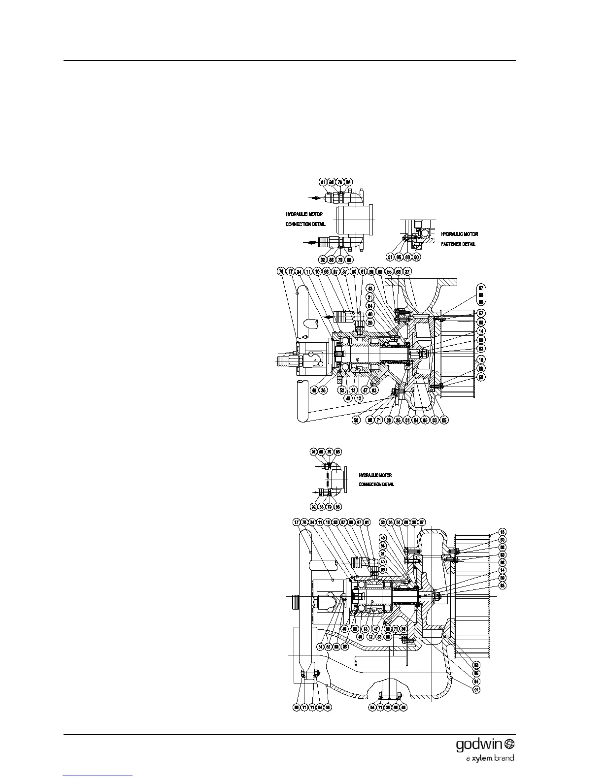
Horizontal and vertical discharges pumps are
available. Only one representative type of each
pump has been illustrated for clarity.
1. If not previously done remove the stud
adaptor (87) and associated fittings and
drain the bearing bracket of hydraulic oil.
2. Remove plug (83) and drain the seal housing
of oil.
3. HS100 pumps: -Undo set screws (56)
holding lifting bracket (17) to the pump body
(1).
HS150 pumps: - Undo nuts (64) from bolts
(55) holding lifting bracket (17) to the
extension pipe (6) and screws (59) holding
lifting bracket to the pump body (1).
Remove lifting bracket.
4. Undo set screws (HS100 – 57; HS150 – 60)
holding the strainer (16) to the pump body
(1). Remove strainer.
5. Release the screws (HS100 – 55; HS150 -
58) holding the bearing bracket, wear plate
and impeller assembly to the pump body
(1). (NOTE. These are the screws on the
larger PCD. The screws on the smaller
PCD retain the wear plate to the bearing
bracket).
6. Extract the bearing bracket assembly from the
pump body (1). The front wear plate (5) can be
removed from the pump body if required by
removing the screws (HS100 – 58; HS150 - 59).
7. Place a bar through the vanes of the impeller
(3) to lock it in position and prevent rotation.
Unscrew (RH thread) and remove the impeller
retaining nut (63) and washer (14). Note that
the nut has a nylon insert that provides a self-
locking function. The nut will therefore remain
stiff to turn until this nylon insert is clear of the
shaft.
8. Pull the impeller (3) off the shaft (13) and
remove the key (9). Two off M10 tapped jacking
screw holes are provided in the boss of the
impeller if required to aid in its removal.
9. Release the screws (HS100 – 55; HS150 - 58)
holding the rear wear plate (4) to the bearing
bracket assembly. Remove the wear plate to
expose the mechanical seals (40 & 39). The
wear plate contains a seal seat (20) that is
removed by releasing the circlip (43).
10. Slide the mechanical seals (40 & 39) off the
shaft (13) and extract the seal seat from the
bearing bracket (10).
Figure 7 Typical HS100 pump
Figure 6 Typical 15022 pump