Book No.: 95-0014-0000/A OPERATOR
Issue: 06 HANDBOOK
Page 23 of 30
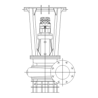
7.5.2.2 IMPELLER FITTING
The impeller is fitted to the tapered shaft by
means of a tapered sleeve with an adjusting
screw locked onto the shaft with a screw and
washer (Figure 27).
Figure 27 Impeller & fittings
Inspect the end of the shaft for any damage, remove any burrs and polish off any flaws with fine emery cloth.
Lightly apply grease film to the shaft end and remove any surplus grease from the taper.
Lightly apply a grease film to the inside of the tapered sleeve and remove any surplus grease.
Lightly grease the threads of the adjustment screw if needed, remove any surplus grease.
NOTE! The impeller can become loose. Remove any surplus grease from the conical and cylindrical surfaces of the
shafts and sleeves.
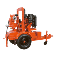
Important: Before any assembly begins rotate the adjustment screw until
it is level with the sleeve (Figure 28). This is the initial setting up point for
the impeller.
The adjustment screw has a left hand thread. Turning it clockwise
moves it outward and turning it anti-clockwise moves it into the sleeve.
The adjustment screw is used to adjust the clearance between the
impeller and the insert ring (wear plate).
Figure 28 Taper sleeve and adjustment screw
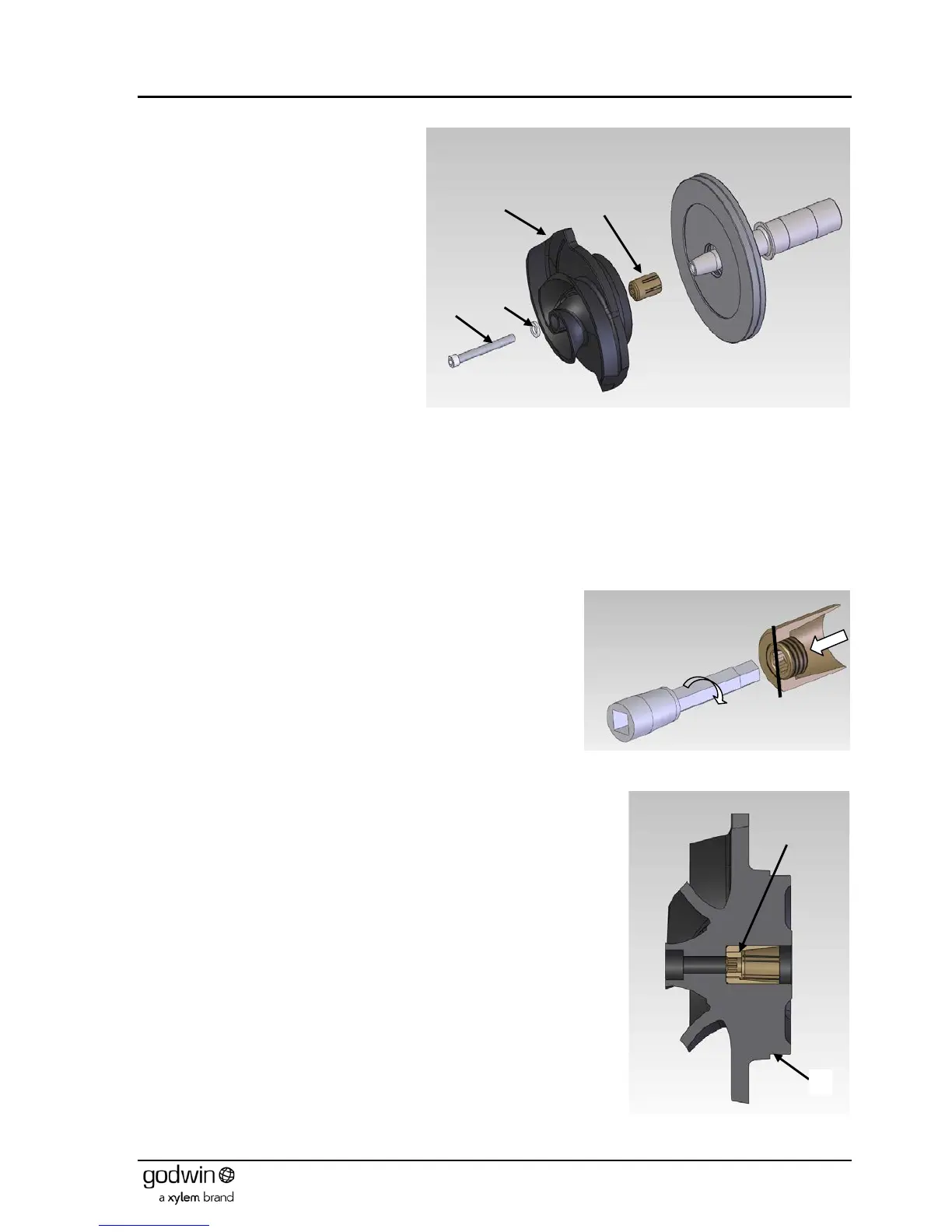
Insert the taper sleeve (2) complete with adjustment screw (3) in its correct
position into the impeller (1) (Figure 29).
Lightly lubricate the impeller cap head screw.
Load impeller complete as above on the shaft.
Insert the impeller cap head screw with its plain washer and hand tighten, this
will ensure the impeller is in the correct position on the taper, and prevent the
impeller falling off during further assembly.
Continue with assembly, attaching the bearing bracket/impeller assembly to the
volute.
Figure 29 Impeller, sleeve and adjustment screw