OPERATOR Book No.: 95-0014-0000/A
HANDBOOK Issue: 06
Page 14 of 30
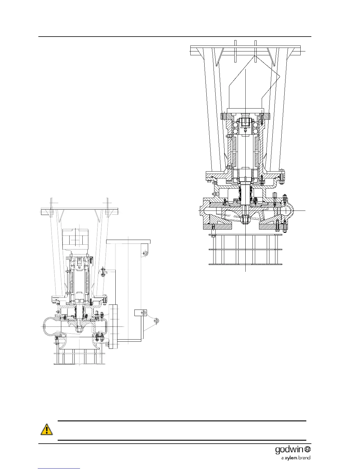
11. Release the nuts (69) from bolts (54) and remove the
lifting bracket (11) and adaptor (8) from the bearing
bracket assembly.
12. Release the screws (57) holding the hydraulic motor (84)
to the bearing cover (77) and remove the motor.
13. Undo the screws (61) and remove the bearing cover (77)
from the bearing bracket (75).
14. Press the shaft assembly out of the bearing bracket from
the pump end.
15. The pump end bearing cover (76) can be removed from
the bearing bracket (75) by releasing the bolts (55).
16. Press the roller bearing (89) outer race out of the bearing
bracket.
17. Flatten the tags on the locking washers (92), prevent the
shaft from rotating, and unscrew the bearing locknuts
(91).
18. Pull the angular contact ball bearings (2 off 90) off the
shaft and remove the bearing spacer (78).
19. Pull the roller bearing (89) inner race off the shaft.
Dismantling is now complete. Inspect all parts for damage or
wear.
7.3.2 Reassembly
New seals and O-rings must be fitted when reassembling. It is also prudent to fit a new impeller retaining nut.
1. Heat the roller bearing (89) inner race and both angular contact ball bearings (2 off 90) with a temperature
controlled bearing heater until they are a consistent 110°C. Do not overheat or allow the bearings to remain at this
temperature for longer than their fitting time.
CAUTION. Bearing races must be pressed into position and not hammered either directly or by drift. Direct
hammering will damage the bearing or rollers. Drift hammering will introduce swarf into the assembly. Either
will result in early bearing failure.
Figure 12 Typical HS150HH pump