OPERATOR Book No.: 95-0014-0000/A
HANDBOOK Issue: 06
Page 8 of 30
7 MAINTENANCE
In this section it is assumed that the pump: -
has been removed from its operating position
has been drained of pumped product
has been drained of hydraulic oil
all hoses have been disconnected
7.1 HS80 pumps
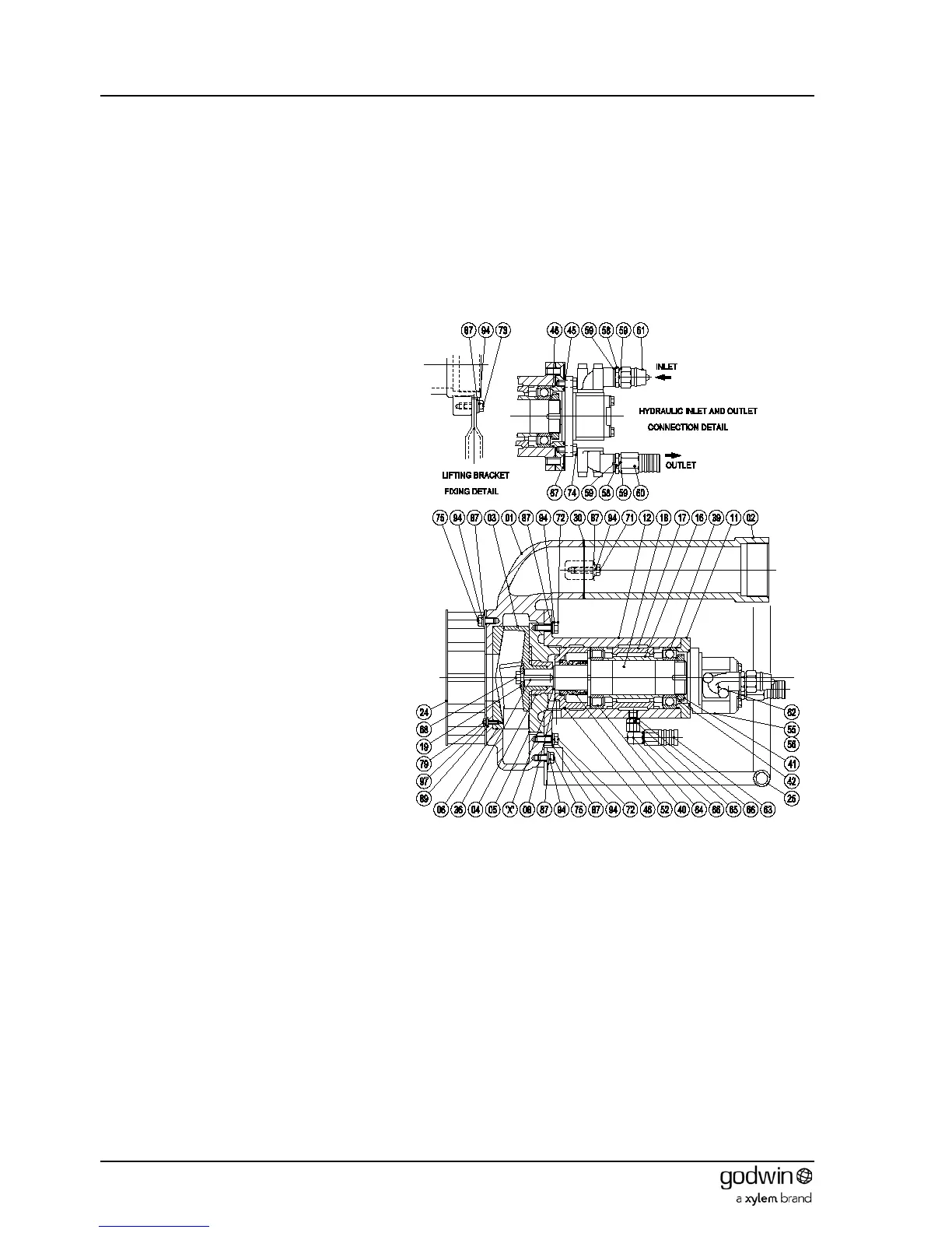
7.1.1 Dismantling
1. Undo set screws (75) holding lifting
bracket (25) to both the pump body (1)
and outlet pipe (2). Remove lifting
bracket.
2. Undo set screws (75) holding the strainer
(24) to the pump body (1). Remove
strainer.
3. Release the screws (72) holding the
bearing bracket, wear plate and impeller
assembly to the pump body (1). (NOTE.
These are the screws on the larger PCD.
The screws on the smaller PCD retain the
wear plate to the bearing bracket).
4. Extract the bearing bracket assembly
from the pump body (1). The extension
pipe (2) and front wear plate (6) can be
removed from the pump body (1) if
required by removing the respective
screws (71) or (79).
5. Place a bar through the vanes of the
impeller (3) to lock it in position and
prevent rotation. Unscrew (RH thread)
and remove the impeller retaining screw
(68) and washer (19). Note that the screw
has a nylon plug through it that provides a
self-locking function. The screw will
therefore remain stiff to turn until this
nylon plug is clear of the shaft.
6. Remove the impeller (3) and the wearing
sleeve (4). Remove the impeller shims (if
any were fitted) noting the number and
thickness for comparison on rebuild.
Remove the key (36).
7. Release the screws (72) holding the rear wear plate
(5) to the bearing bracket assembly. Remove the
wear plate to expose the mechanical seal housing (8).
8. Extract the mechanical seal housing (8) complete with O-ring (46) from the bearing bracket (12). The stationary
seat of the mechanical seal will probably stay in the seal housing and can be removed by pressing out.
9. Carefully extract the mechanical seal (52) from the bearing bracket.
10. Release the screws (74) holding the hydraulic motor (55) to the bearing cover (11) and remove the motor.
11. Undo the screws (67) and remove the bearing cover (11) from the bearing bracket.
12. Press the shaft assembly out of the bearing bracket from the pump end.
13. Flatten the tags on the locking washer (42), prevent the shaft from rotating, and unscrew the bearing locknut (41).
14. Pull the ball bearing (39) off the shaft and remove the bearing outer (17) and inner (16) spacers.
15. Pull the roller bearing inner race (40) off the shaft.
Dismantling is now complete. Inspect all parts for damage or wear.