Book No.: 95-0014-0000/A OPERATOR
Issue: 06 HANDBOOK
Page 5 of 30
5 INSTALLATION
5.1 General Notes
Xylem Dewatering Solutions may refute warranty liability if the installation does not meet the requirements of the pump.
Consult Xylem Dewatering Solutions should any doubt exist over the suitability of an installation.
Only suitably qualified personnel (both mechanical and electrical) should carry out the installation. All local and national
regulations in force must be observed.
The delivery pipe work should be kept as short as possible with a minimum number of large radii bends to minimise
pipe friction losses. Fitting larger diameter pipe work than the pump outlet will maximise flow rates. Size increases in
the horizontal plane should be achieved using eccentric reducers to minimise the risks of air locks.
Lay out above ground piping runs before connecting to the pump to ensure that tight bends and other flow restrictions
are not included.
5.2 Hydraulic motor
CAUTION. Hydraulic motors on submersible pumps can suffer serious damage, including catastrophic failure, if
they are operated in the wrong rotation.
This occurs when either the hydraulic pipe connections are made incorrectly; i.e. inlet line to the outlet side of the motor
and vice versa or, a wrong rotation motor is fitted on replacement. Failures result in unnecessary down time and
possible pollution from escaped hydraulic fluid. Correctly specifying a replacement motor and identifying the inlet and
outlet motor ports on new or existing motors before connection and start up is critical.
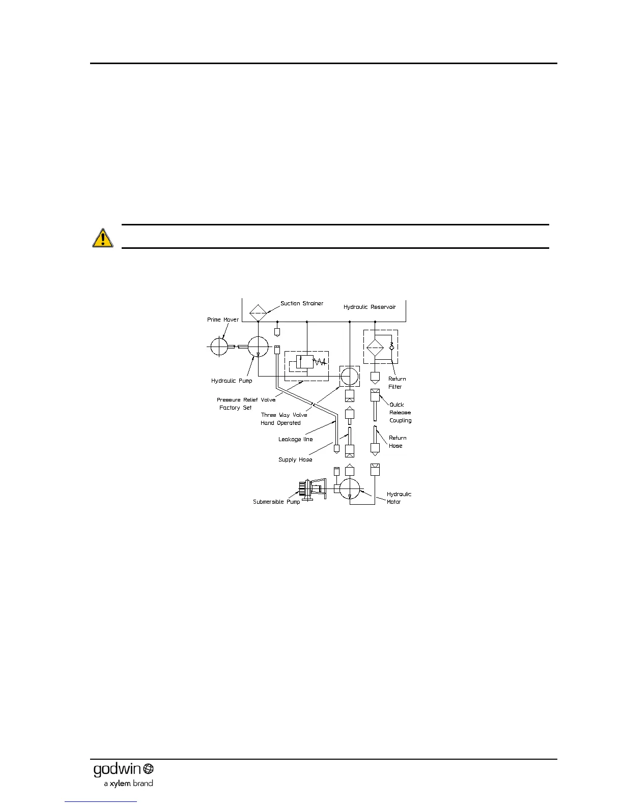
Figure 1 Hydraulic system schematic
A Xylem Dewatering Solutions supplied system is fitted with male and female quick release couplings at all terminal
points to prevent incorrect connection. A typical system illustrating this is shown in Figure 1.
5.2.1 Determining motor inlet and outlet ports
Many older motors have their bolted on connecting ports stamped with ‘IN’ or ‘HIGH PRESSURE’. These stampings
should be treated with a degree of caution as the ports could have previously been removed from the motor and
replaced incorrectly. Later motors will have their rotation and ‘IN’ stamped on the body (see Figure 3). These may be
taken as much more reliable, but even so caution must be exercised and the user must be satisfied that they are
correct before proceeding.
The Xylem Dewatering Solutions serial number of the pump is vitally important in any request for spares. It will be found
on a serial plate located on the main body of the pump. If the serial number cannot be found then the following
procedure should be employed to determine the requirement.
It is important to understand that when specifying any directional rotation it must be qualified by stating the direction in
which that rotation is viewed. This is illustrated in Figure 2 where, when viewed from above the submersible pump, the
direction of rotation is clockwise, but the Xylem Dewatering Solutions method of specification is the direction of rotation
looking from the underside (i.e. the inlet side) of the pump and is anti-clockwise. Figure 2 shows a Heidra 10022
submersible pump but the principles are equally applicable to any submersible pump.
1. Identify the submersible pump rotation – clockwise or anti-clockwise? (Refer to Figure 2).
2. The hydraulic motor rotation notation is the same as the pump; i.e. an anti-clockwise pump requires an anti-
clockwise motor and vice versa.