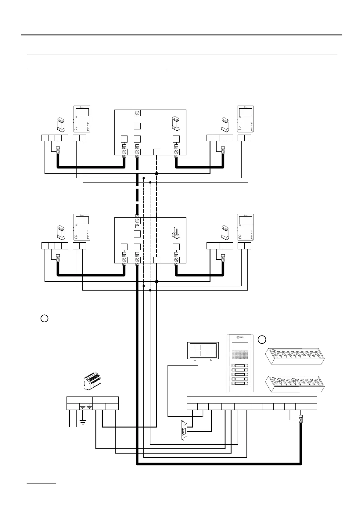
WIRING DIAGRAMS
18
FA-Plus/C or FA-Plus
SEC
PRI
~~
Mains
+ +
--
Place this power supply
as close as possible to
the first distributor.
Remove the JP1 jumper
from all of the distributors
except the last.
CN4
CN4
CN4
CN4
E
E
D1
D1
D2
D2
+
+
D4L-PLUS
D4L-PLUS
JP1
JP1
S
S
SW1
SW2
M =Master.
M
D
Mesh
Vin-AinAout Vin+ Vout-Vout+
CN1
+
-
+CV1CV2
-
10
1
9
2
8
3
7
4
6
5
CN3
DC lock
release
Video door entry system with coaxial cable:
Important:
For further information about the door panel, sections, distances, wiring diagrams, etc., see the T632 PLUS P/T manual.
https://doc.golmar.es/search/manual/50122328
Tekna HF Plus Tekna HF Plus
Tekna HF Plus Tekna HF Plus
A
_
+
D
V
in
V
out
CN3
CN2
A
_
+
D
V
in
V
out
CN3
CN2
A
_
+
D
V
in
V
out
CN3
CN2
A
_
+
D
V
in
V
out
CN3
CN2
TEKNA PLUS MONITORHF