6
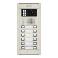
The monitor features an RJ-45 connector for installation with a UTP cable. It is
located on the left-hand side of the back of the monitor.
It enables connection of the system's main communication wires (+, -, A, D, Vp
and Mp) in twisted-pair installations.
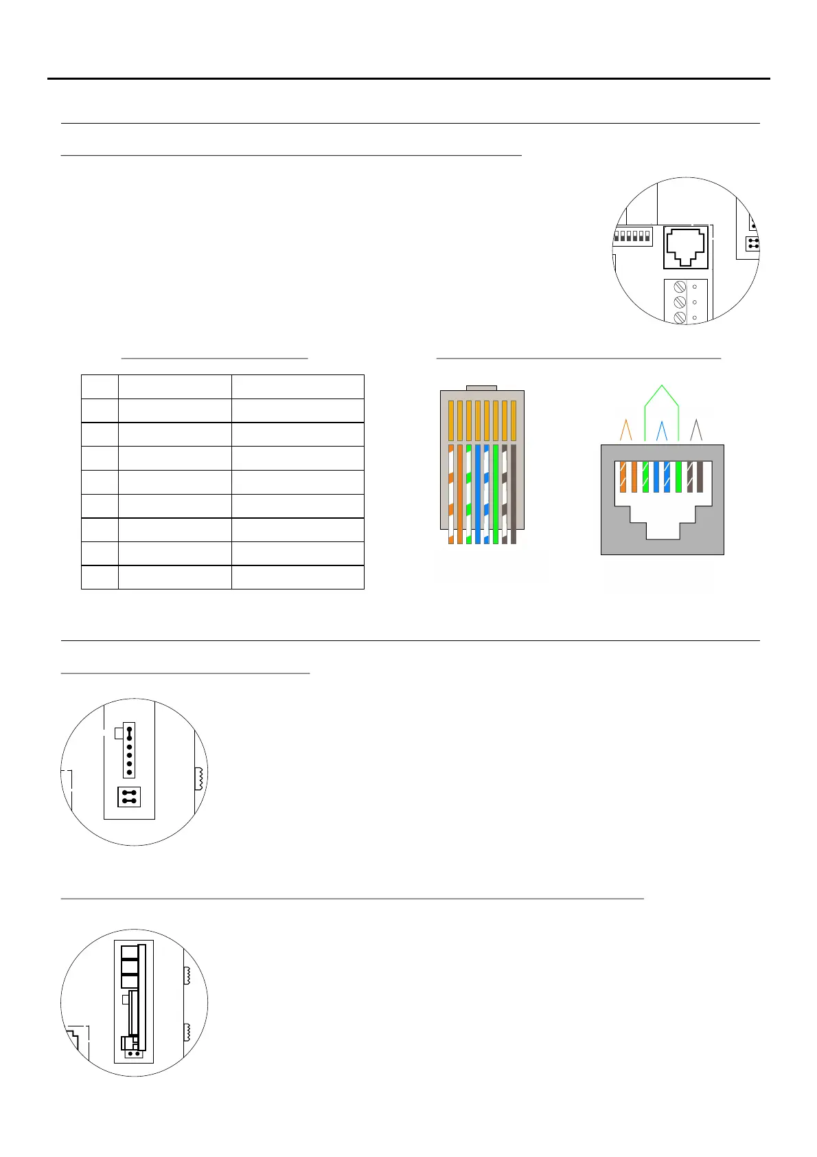
RJ-45 connector (cable type: T568B)
Male connector Female connector
PAR 2 PAR 1 PAR 4
PAR 3
1 2 3 4 5 6 7 8
1 2 3 4 5 6 7 8
Ethernet cable
Golmar connection
White + Orange
GND (Audio)
Audio
GND (Dat )a
+18V
+18V
Data
Vp
White + Brown
Mp
RJ-45 equivalence table
Description of the RJ-45 connector (installation with UTP cable):
Pin
1
2
3
4
5
6
7
8
Orange
White + Green
Blue
White + Blue
Green
Brown
Locate the CN4 connector at the back of the monitor.
To insert the EL-562S module, first remove the jumper located in the CN4 connector and
JP1 of the monitor.
NOTE: In this type of installation, set the SW1-3 DIP switch on the sound module of the
door panel to ON, see the instruction manual (p. 13) or set the SW1-3T632/Plus P/T
DIP switch of the EL500SE microprocessor to ON, see the manual (p. 7).T5000 ML
The door panel of the SV801SE GRF kit does not require modification.
Use the specific wiring diagram.
The end of line jumper is located on the CN4 connector at the back of the monitor.
In the case of twisted pair installations, the end of line jumper is located in the EL562
module (see next section).
Do not remove the jumper if the video cable ends in the monitor. Remove the jumper if the
video cable continues after the monitor.
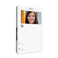
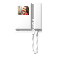
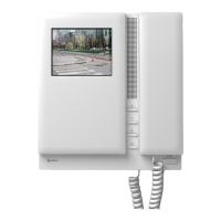
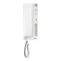
DESCRIPTION OF THE MONITOR
MONITOR SETTINGS
Handling of the end of line jumper:
EL-562S module for video door entry system installations with twisted pair cable:
TEKNA PLUS MONITORHF