08
2.3 Electrical Wiring Connection
2.3.1 System connection diagrams
Meter
L1
L2
L3
N
PE
L1
L2
L3
N
PE
L1
L2
L3
N
L1
L2
L3
N
PE
Distribution box
On-Grid
Back-Up
RCD
Normal Loads
L1 L2 L3 N
PE
PE
Grid
Hybrid Inverter
or
N
PE
Back-Up
Loads
Smart
Meter
E-BARE-BAR
RCD
Battery
BMS
PV String
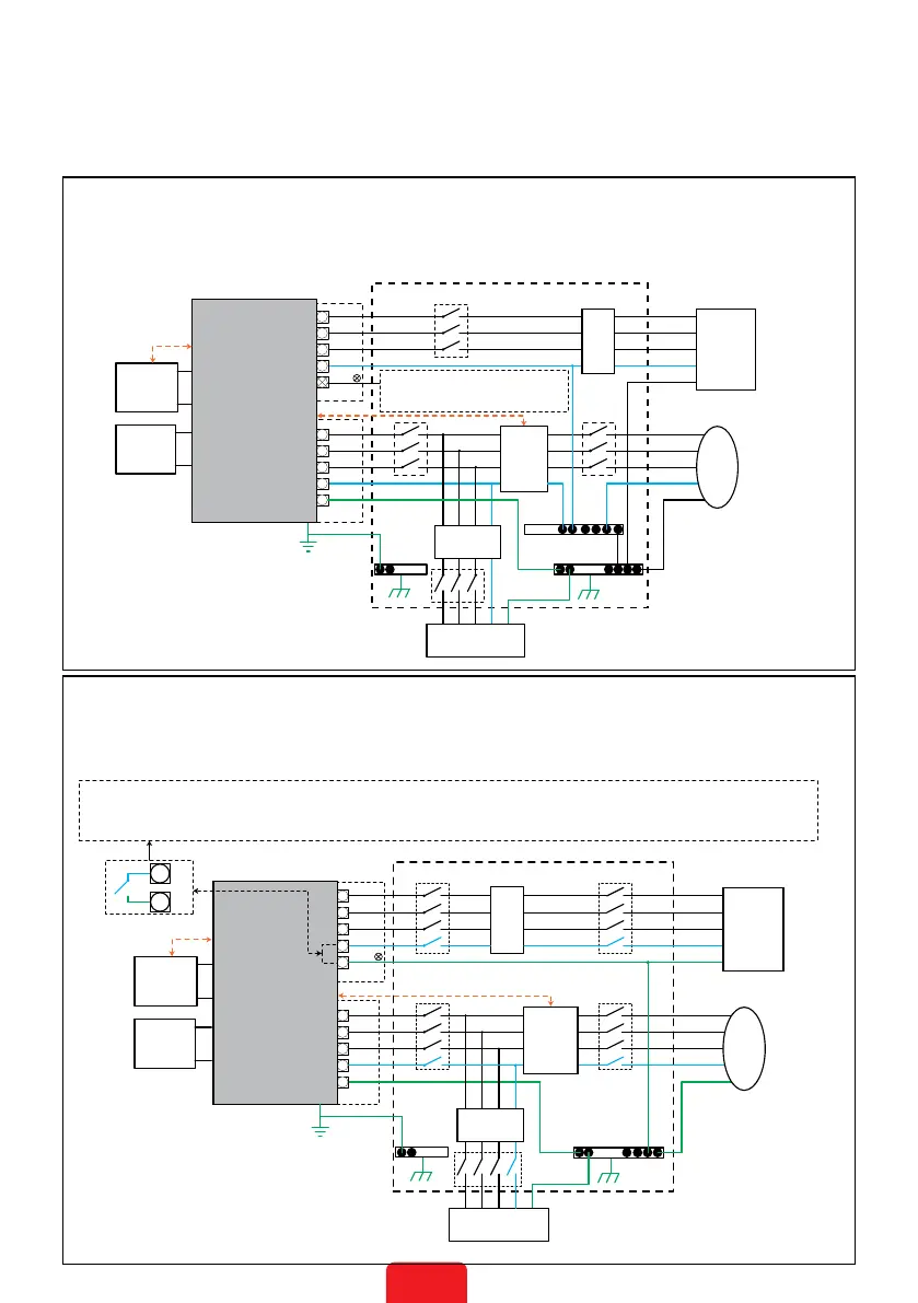
AccordingtoAustralianregulations,theNwiresontheGRIDsideandBACK-UPsideshouldbe
connectedtooneterminalblock.Otherwise,theBACK-UPfunctionmayfail.
ThefollowingdiagramshowsthewiringconnectionwhentheNwireandthePECableareconnectedtothe
sameterminalblock.
EquipmentinstalledinAustralia,NewZealand,SouthAfrica,andsoonshouldfollowthisdiagram.All
installationsandwiringconnectionsshouldmeetlocallawsandregulations.
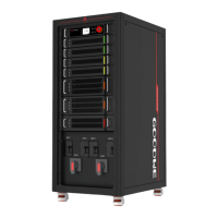
ThefollowingdiagramshowsthewiringconnectionwhentheNwireandthePECableareconnected
separately.
EquipmentinstalledinChina,Germany,CzechRepublic,Italy,andsoonshouldfollowthisdiagram.All
installationsandwiringconnectionsshouldmeetlocallawsandregulations.
WhentheinverterisworkinginBACK-UPmode,theNwireandPEcablewillbeconnected
inoneinternalrelay.Thisrelaywillbedisconnectedwhentheinverterisworkingingrid-
tiedmode.
Distribution box
On-Grid
Back-Up
Battery
Meter
L1
L2
L3
N
E-N
Link
Smart
Meter
RCD
N-BAR
Hybrid Inverter
E-BAR
BMS
E-BAR
RCD
orPE
L1
L2
L3
N
PE
L1
L2
L3
N
PE
L1
L2
L3
N
PE
L1 L2 L3 N
PE
Back-Up
Loads
Normal Loads
Grid
PV String
DisconnectthisterminalwhentheN
wireandthePEcableareconnected
tothesameterminalblock.
 Loading...