Version: V1.2 21
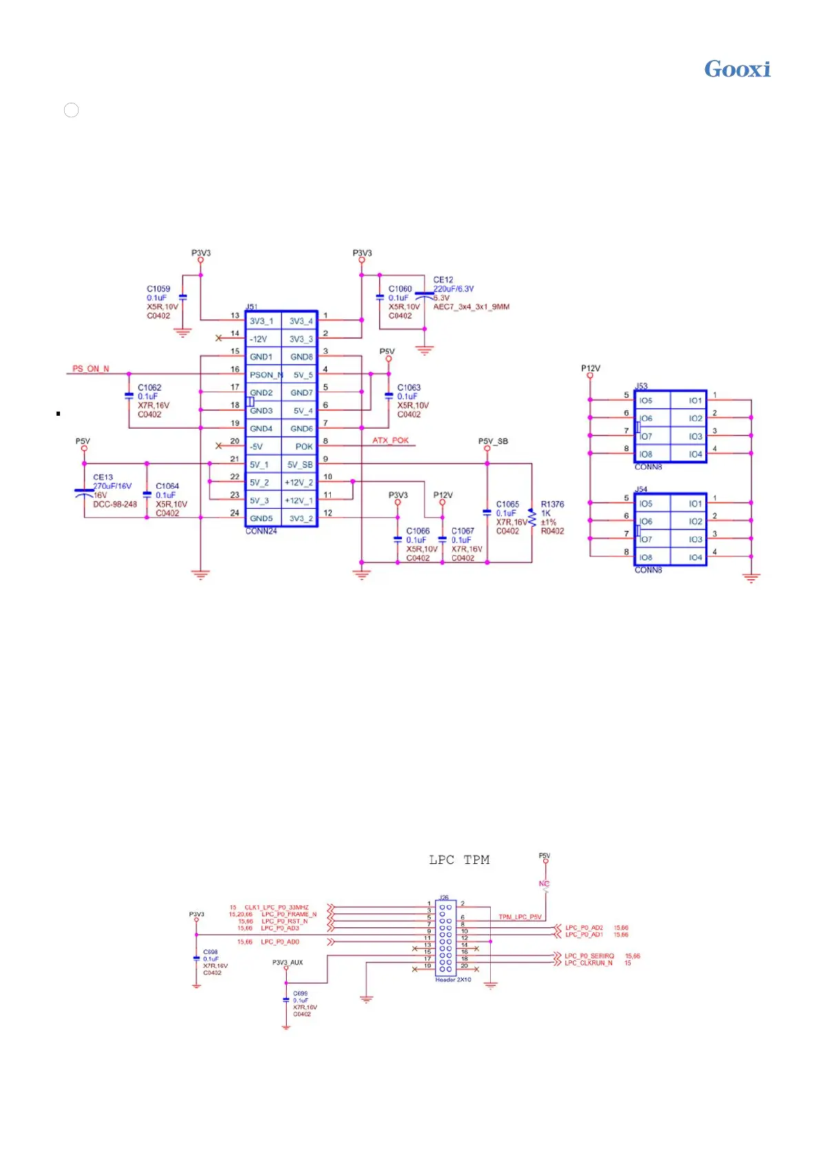
2/3/5/6/7) Power connector (J51/J53/J54)
8
2x12pin ATX power connector with 4.2mm spacing, single pin supports 6A when the wire diameter is 18AWG;
②③ is 2x4 ATX power connector with 4.2mm spacing, single pin supports 7A when the wire diameter is 18AWG;
⑤⑥ is 2x3 ATX power supply with 4.2mm spacing connector, single pin supports 7A when the wire diameter is
18AWG. When the motherboard is working at full load, all power supplies need to be connected.
Note: The connector connection conforms to the ATX power specification, and the ATX power can be directly used
for power during the debugging stage.
Figure 2-13
4) PMBUS interface
The motherboard supports the power PMBUS management protocol
8) 2 MiniSAS SFF-8643 ports
The motherboard supports the connection of 8 SATA hard disks through 2 MiniSAS SFF-8643 interfaces.
9) M.2 slot
The motherboard supports the installation of 1* 2280 M.2 SSD, only supports PCIe protocol, and does not support
SSD with SATA protocol.
10) LPC TPM expansion interface
The motherboard provides an LPC TPM expansion interface, using 2x10Pin NC Pin4 2.54mm pins, the detailed
signal definition is as follows:
Figure 2-14
11) Front USB3.0 connector
 Loading...