Version: V1.2 22
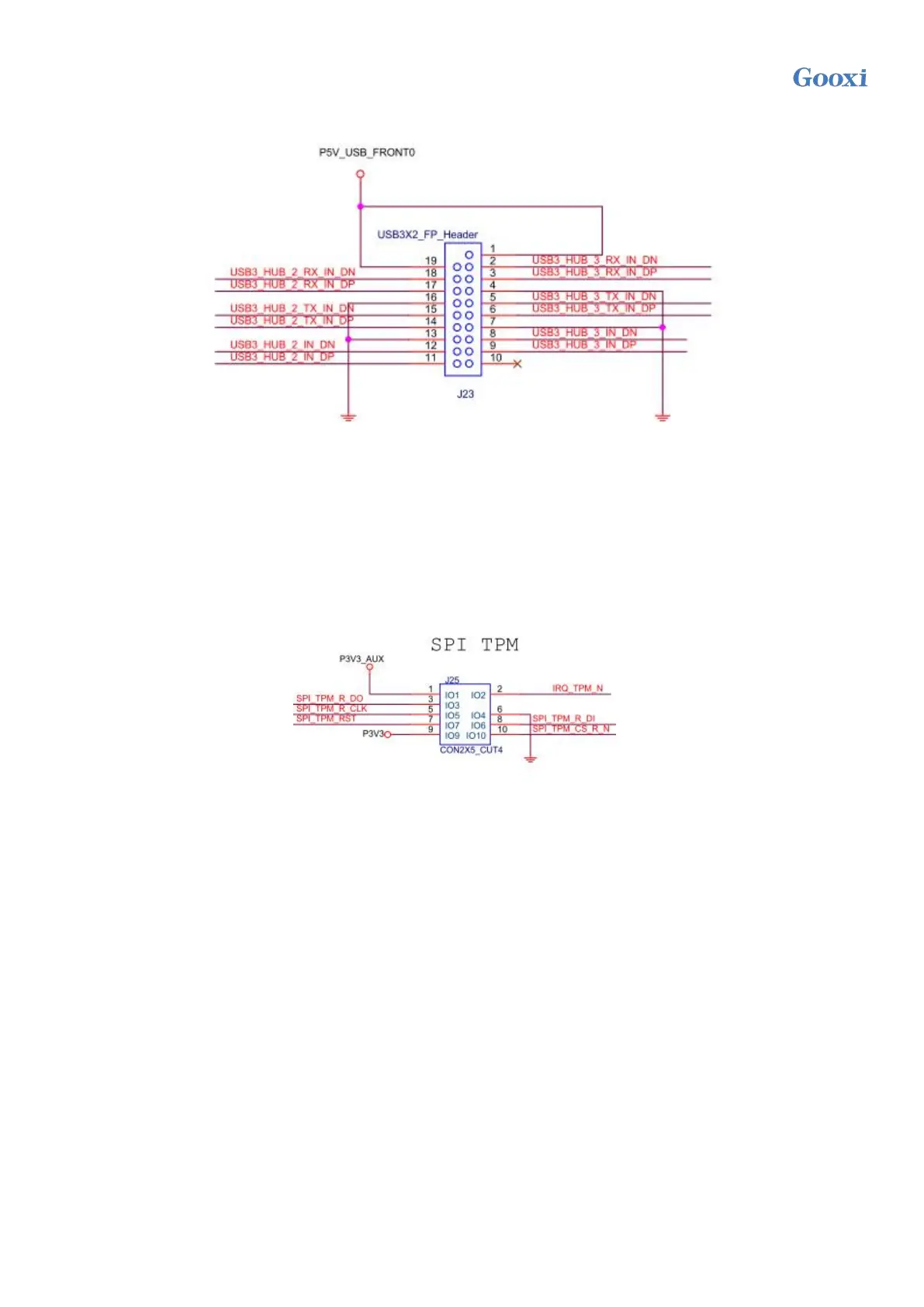
The side ear USB3.0 connector is 2x10pin 2.0mm spacing with fenced pins, the detailed signal definition is as
follows:
Figure 2-15
12) Front VGA connector
The motherboard provides a VGA interface that can be connected to the front panel for connecting to a VGA monitor
and outputting host information.
13) SPI TPM extension interface
The motherboard provides a SPI TPM expansion interface, using 2x5Pin NC Pin4 2.54mm pins, the detailed signal
definition is as follows:
Figure 2-16
14/15/16/17/18/19/20/21/22/23) PCIe SLOT
There are 10 standard X16 PCIe slots J1/J2/J3/J4/J8/J9/J10/J11/J12/J13 on the motherboard, of which 6 are PCIe
4.0 x8 (in PCIe 4.0 x16 slot) and 4 are PCIe 4.0x16 (in PCIe 4.0 x16 slot) 2, 6, 7, 10 slots). The third slot of the PCIe
Switch is designed as x8 or no signal, and the fourth slot is designed as x8 or x16.
 Loading...