GMC-I Messtechnik GmbH 15
Testing the LED which Indicates the Detection of External Voltage
when Switched Off – OFF Switch Position
Ð Apply a voltage of greater than 50 V (+ and COM jacks).
Ð Turn the rotary switch to the V position.
Ð Read the voltage value at the LCD.
Ð Turn the rotary switch to the OFF position.
Test results: If applied voltage is unchanged and the LED which
indicates the detection of external voltage lights up red, the LED is
OK. In this case, the LED reliably indicates external voltage even
when the instrument is switched off. We recommend executing
this test at regular intervals.
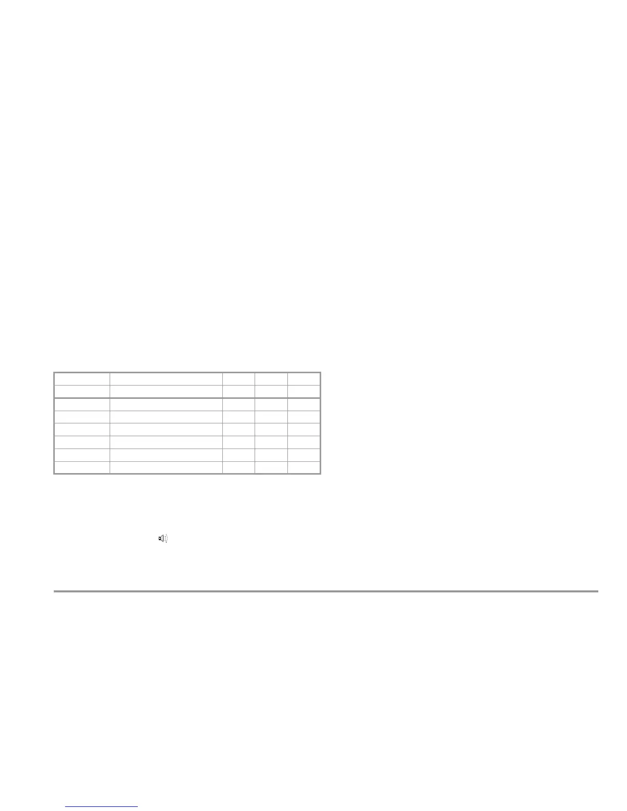
Limit Values for Insulation and Low-Resistance Measurements
Acoustic Signals
Exceeded limit values can also be indicated acoustically by set-
ting the beeP parameter to on (see page 12).
The loudspeaker symbol appears in this case.
4.2 Measured Value Display
The following appear at the LCD panel:
• Measured value in digital format
• Measured value in analog format as bar graph or pointer
• Unit of measure
Measured values for automatic measuring sequences are
retained at the display as digital values until the next measure-
ment sequence is started, or until automatic shut-off occurs.
If the upper range limit is exceeded, 0L appears at the display,
thus indicating overranging.
If the lower range limit is fallen short of, ur appears at the display,
thus indicating underranging.
Either a bar graph or a pointer can be selected for the analog dis-
play (see AdiSP parameter on page 12).
METRISO G1000 G500
G500MM
(M550C) (M550D) (M550E)
Limit R
ISO
/ R
INS
50 k @ U
ISO
/U
INS
= 50 V 33
3
100 k @ U
ISO
/U
INS
= 100 V 33
3
500 k @ U
ISO
/U
INS
= 250 V 33
3
1M @ U
ISO
/U
INS
= 500 V 33
3
1M @ U
ISO
/U
INS
= 1000 V 3 ——
Limit R
LO
2 33—

 Loading...


