Checking the Measurement Cables
Before performing insulation measurement, the test
probes on the measurement cables should be short-cir-
cuited in order to assure that the instrument displays a
value very close to 0 (see section 8).
This makes it possible to detect interrupted measurement
cables, which simulate high insulation resistance.
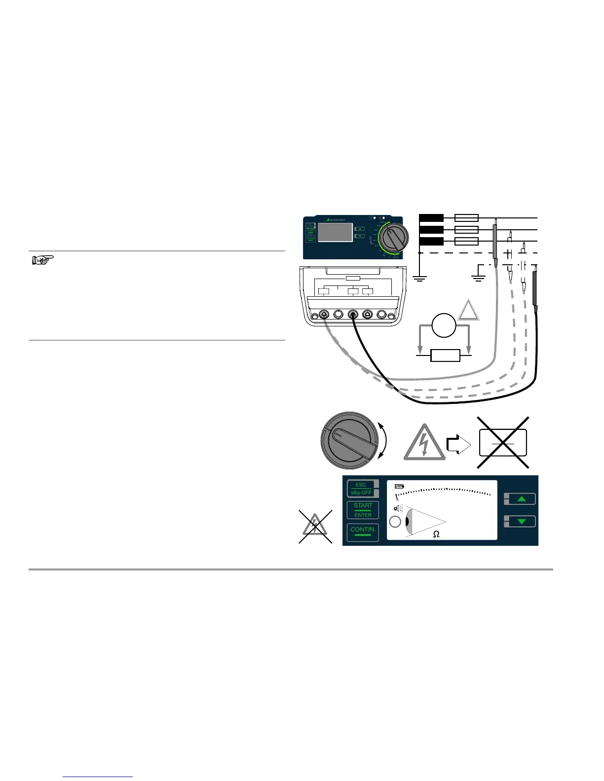
Ð Connect the device under test to the + and COM jacks.
Sample connection layouts for insulation resistance measurement
are included in section 14.1.
Insulation resistance can only be measured at voltage-free
objects. If mains voltage or external voltage is applied to the mea-
surement inputs, measurement cannot be started. This is indi-
cated by the high-voltage symbol which appears at the display.
5.2 Performing the Measurement
Note: Condensation must be ruled out when performing measure-
ments at close to the freezing point.
Ð Select the measuring function and the desired test voltage
with the rotary switch, e.g. R
iSO
100V.
The momentarily selected test voltage (nominal voltage) appears
in the bottom right-hand corner of the display.
Ð Start an individual measurement by briefly pressing the START
key, or initiate continuous measurement by briefly pressing
the CONTIN key.

 Loading...


