GP3D Root User Manual
9
4. INTERFACE AND FUNCTION
4.1. INTERFACE
4.1.1 Turn on the power switch, and double click “Germinate” on the
desktop icon to open the software.
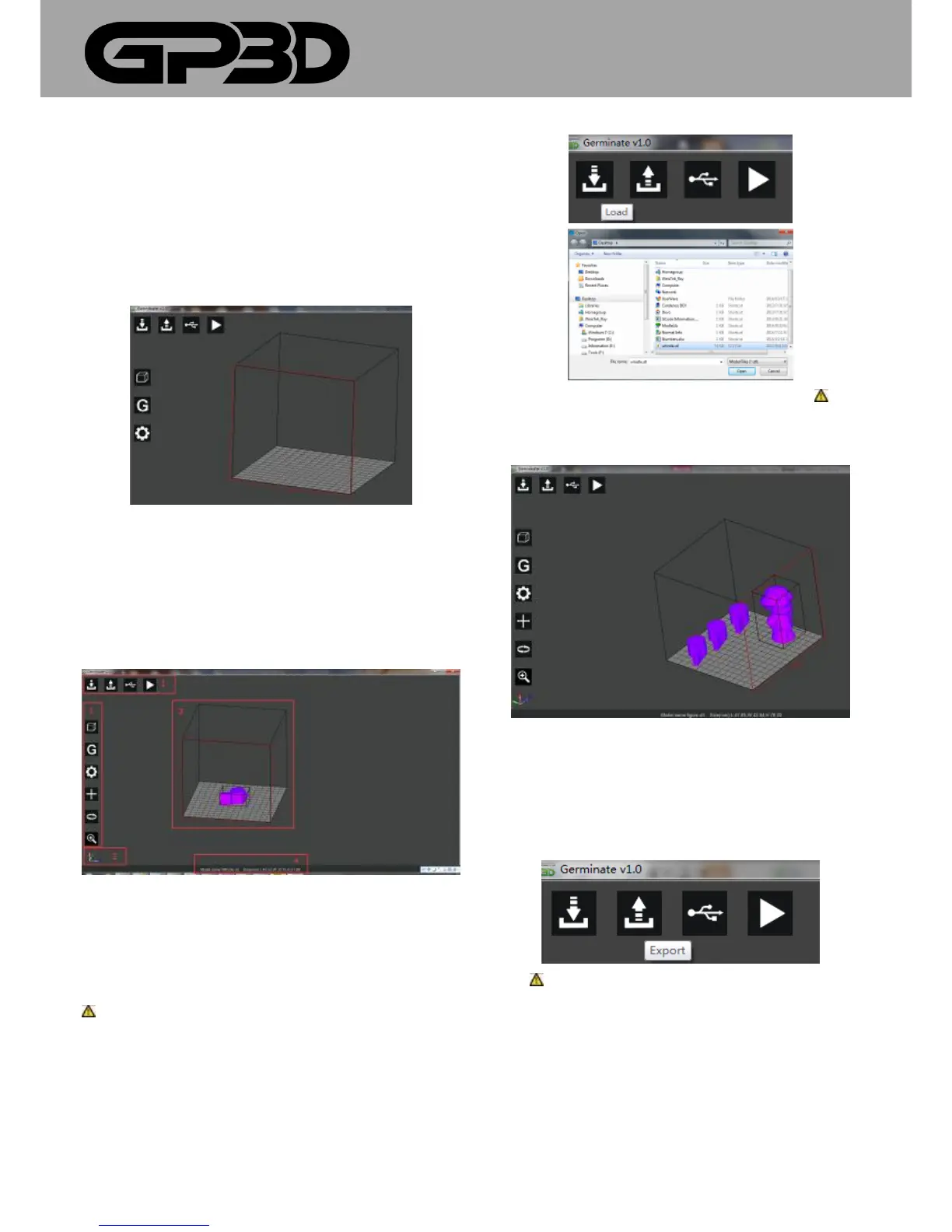
4.1.2 In the software interface, the bar “1” at the top left corner is the
function menu. Move the mouse to the menu icon and the corresponding
functional description will be displayed; the bar “2” at the lower left
corner is schematic three-dimensional coordinates; the middle bar “3” is
model display area, and the side with red lines faces the operator; the
bottom bar “4” is for status display, indicating the temperature and model
information.
4.1.3 Import model
4.3.3.1 Click the icon “Load”, and the dialog pops out to look up the
model path. After selecting the model, click “Open”. The model with
imported software is as shown in Figure 4.3.2.
Notice: if you want to open a previously generated GCODE file, you
need to store the STL file and the GCODE file in the same folder. Import
the STL file to open the GCODE file, without a new GCODE.
4.1.4 Click “Load” again, and you can import multiple models. Notice:
Do not import more models than the platform area allows, otherwise the
models printed may overlap.
4.1.5 Generate a file
4.3.4.1 Click the icon “Export”, and the dialog box to save the
file path pops out. Select the save path and click “Save”, and
software automatically generates the printing from USB flash
disk file.
4.1.5.1 Notice: do not modify the file extension when you save an
offline file, otherwise the printer will not recognize the file.