6 310543
Setup
Ground the System
WARNING
FIRE AND EXPLOSION HAZARD
To reduce the risk of a fire, explosion,
and serious injury, proper electrical
grounding of every part of your system is
essential. Read the warning section,
FIRE AND EXPLOSION HAZARD, on
page 5 and follow the grounding
instructions below.
The following grounding instructions are minimum
requirements for a basic dispensing system. Your
system may include other equipment or objects which
must be grounded. Check your local electrical code for
detailed grounding instructions for your area and type
of equipment. Your system must be connected to a
true earth ground.
1. Pump: ground the pump by connecting a ground
wire and clamp as described in your separate
pump instruction manual.
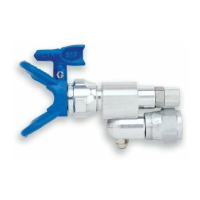
2. Automatic metering valve: ground the metering
valve by connecting it to a properly grounded fluid
hose and pump.
3. Air compressor: ground the equipment according
to the manufacturer’s recommendations.
4. Air hoses: use only electrically conductive air
hoses.
5. Fluid hoses: use only electrically conductive fluid
hoses.
6. Fluid supply container: ground according to the
local code.
7. Object being sprayed: ground according to the
local code.
8. All solvent pails used when flushing: ground ac-
cording to local code. Use only metal pails, which
are conductive, placed on a grounded surface. Do
not place the pail on a non-conductive surface,
such as paper or cardboard, which interrupts the
grounding continuity.
Installation
NOTE: Read this manual thoroughly before installing
the automatic metering valve.
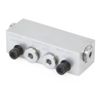
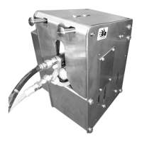
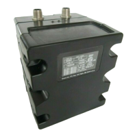
The metering valve has a tapped hole for mounting,
making it ideal for automatic systems and for use in
multiple manifold high production operations. The
valve can be supplied by any standard Graco pump.
1. Inspect the metering valve for shipping damage. If
damage is found, notify the carrier immediately.
2. Attach the meter to its mounting fixture by means
of the 7/16–20 tapped mounting hole in the valve
body (18). Keep in mind that the height of the
valve must be adjustable so either the part or the
valve can retract at the same instant that the valve
shuts off.
3. Connect the actuating air supply (minimum 80
psi/0.55 MPa/5.5 bar) from a three-way, normally
closed air valve to the 1/8 npt(f) air inlet in the air
cap (12). Cycle the valve. Observe the action of
the needle valve (7) and the spring (6) through the
vent hole in the valve body (18).