310543 7
Operation
Pressure Relief Procedure
WARNING
INJECTION HAZARD
The system pressure must be manually
relieved to prevent the system from
starting or spraying accidentally. Fluid
under high pressure can be injected through the
skin and cause a serious injury. To reduce the risk
of an injury from injection, splashing fluid, or mov-
ing parts, follow the Pressure Relief Procedure
whenever you:
are instructed to relieve the pressure,
stop dispensing,
check or service any of the system equipment,
or install or clean the nozzle.
1. Shut off the fluid supply line to the automatic
metering valve.
2. Close the bleed-type master air valve (required in
your system) to shut off the air to the automatic
metering valve.
3. Repeatedly actuate the automatic metering valve
until no fluid flows.
4. Open the pump drain valve to help relieve fluid
pressure in the pump, hose, and automatic meter-
ing valve. Actuating the valve to relieve pressure
may not be sufficient. Have a container ready to
catch the drainage.
5. Leave the drain valve open until you are ready to
dispense again.
6. If you think that the valve nozzle or fluid hose is
completely clogged or that pressure has not been
fully relieved after following the steps above, very
slowly loosen the hose end coupling and relieve
pressure gradually, then loosen the coupling
completely. Clear the nozzle or hose obstruction.
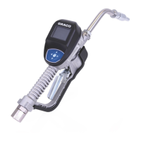
How the Metering Valve Operates
The metering valve is an automatic, air-operated,
single-acting valve for dispensing accurately metered
amounts of fluid repeatedly. The valve can dispense
from 0.2 cc to 4 cc of fluid, with a viscosity range from
3000 to 1 million centipoise.
An air operated spool valve directs pressurized fluid to
either side of a floating piston. Shot size is easily and
quickly changed by simply lengthening or shortening
the piston stroke (see Adjusting the Valve).
At its maximum of 4 cc of moderate viscosity fluid, the
valve will dispense up to 15 shots per minute. Lower
viscosities or smaller shots permit even faster opera-
tion.
A special snuffer action at the end of the dispensing
cycle draws fluid back, preventing dripping or stringing.
Adjusting the Valve
1. Connect the fluid supply line to the 1/4 npt(f) fluid
inlet (C02022) or to the external threads of the
boss (C02021).
2. Gradually apply fluid pressure while cycling the
valve. Increase pressure until the desired dispens-
ing rate is attained and all air is purged from the
fluid supply line.
NOTE: To purge air from the fluid supply line, hold the
valve higher than the fluid source with the hose on a
gentle incline and cycle the valve repeatedly.
WARNING
To reduce the risk of serious injury whenever you
are instructed to relieve pressure, always follow the
Pressure Relief Procedure at left.
3. Relieve the pressure.
4. Install a suitable nozzle in the 1/8 npt(f) fluid outlet
of the retainer (19). See page 20 for available
nozzle sizes.
5. Turn the nut (11) counterclockwise to unlock. Turn
the retainer (19) counterclockwise until it engages
the stop screw (9) but does not hinder the free
sliding action of the needle valve (7).
NOTE: Adjusting the retainer to the extreme open
position may cause the valve to malfunction due to
cocking of internal components.
6. Adjust the shot size by turning the retainer clock-
wise for less fluid, counterclockwise for more fluid.
NOTE: The valve must be cycled and adjusted simul-
taneously when attempting to reduce shot size.