Installation
22 3A6931A
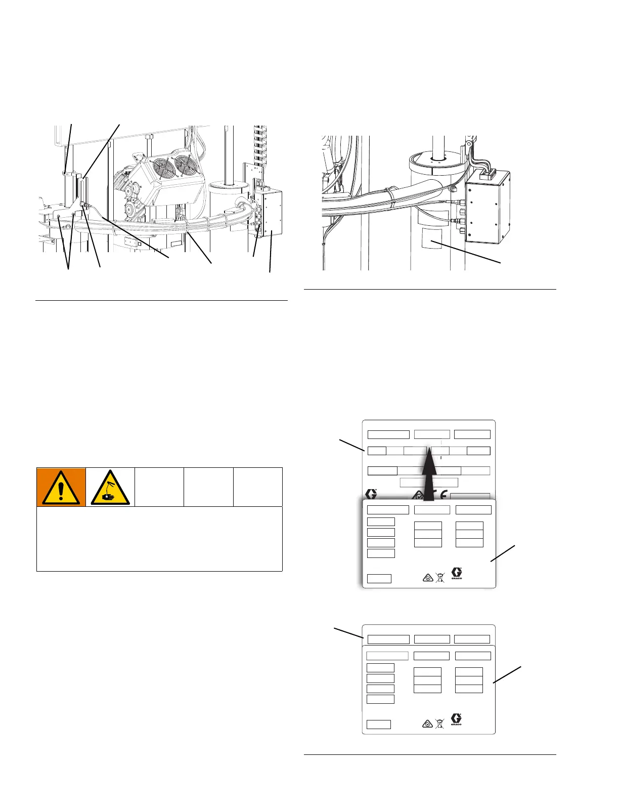
18. Install the empty level sensor.
a. Attach the actuator bracket (321) onto the ram
air cylinder shaft as shown in Figure 39.
b. Install the level sensor bracket (322) using two
screws (310) and washers (309).
c. Attach the level sensor (323) onto the level
sensor bracket (322) as shown in Figure 39.
d. Connect one end of the harness (324) to the
level sensor. Connect the other end of the
harness to the bulkhead connection labeled C3
on the ram junction box (308).
e. Use five wire ties (313) to secure the harness.
19. Verify all components downstream of the pump are
rated to the new, higher pressure. Replace any
components that are not rated to the higher
pressures.
NOTE: Converting from air to electric changes the
operation of the ram supply system. Follow the E-Flo SP
Supply Systems Installation-Parts manual and the E-Flo
SP Software Instructions for complete warnings and
instructions for the system going forward. See Related
Manuals on page 2.
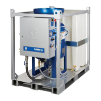
20. The identification label (328,329) included in the kit
needs to be applied on the rear side of the ram
cylinder where the original identification label is
located below the ram junction box mounting
bracket and the safety labels as shown in Figure 40.
NOTE: When you are applying the new label, you must
leave the part number, serial number, and series
showing on the original label. The rest of the original
identification label needs to be covered by the new one
to allow for updated pressure and electrical information.
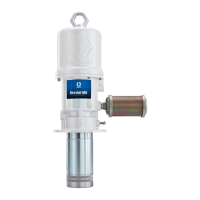
21. Carefully place the new identification label over the
original one so they line up as shown in Figure 41.
FIG. 39: D200s Empty Level Sensor
This conversion results in increased pressure to the
system. To help prevent serious injury from skin injec-
tion, all components downstream of the pump must
be rated to the new, higher maximum pressures. See
the Pressure Ratings table on page 4.
309,310
321
322
323
324
313
308
C3
FIG. 40: D200s Identification Label Location
FIG. 41: Apply Identification Label on D200s
PART NO.
SERIAL NO.
SERIES
MAX AIR WPR
MPa bar PSI
MAX FLUID WPR
MAX TEMP
ºC
WEIGHT
kg
MADE IN
MPa bar PSI
lbºF
BAR CODE TO BE INSERTED HERE
GRACO.COM / PATENTS Artwork No. 291841 Rev. E
GRACO INC.
P.O. Box 1441
Minneapolis, MN
55440 U.S.A.
CMXXXX XXXXX XXXX
.
P.
. Box 1441
nnea
o
s
PART NO.
SERIES
SERIAL NO.
VOLTS
PHASE
AMPS
HZ
MAX FLUID WPR
MPa
bar
PSI
Read instruction manual.
Artwork No. 29A057 Rev. A
GRACO INC.
P.O. Box 1441
Minneapolis, MN
55440 U.S.A.
CUSTOMER MUST SUPPLY
BRANCH CIRCUIT PROTECTION
See www.graco.com/patents
MAX AIR WPR
MPa
bar
PSI
EMYYYYY YYYY YYYYY
I
ER
ERIE
PART NO.
SERIAL NO.
SERIES
MAX AIR WPR
MPa bar PSI
MAX FLUID WPR
MAX TEMP
ºC
WEIGHT
kg
MADE IN
MPa bar PSI
lbºF
BAR CODE TO BE INSERTED HERE
GRACO.COM / PATENTS Artwork No. 291841 Rev. E
GRACO INC.
P.O. Box 1441
Minneapolis, MN
55440 U.S.A.
CMXXXX XXXXX XXXX
PART NO.
SERIES
SERIAL NO.
VOLTS
PHASE
AMPS
HZ
MAX FLUID WPR
MPa
bar
PSI
Read instruction manual.
Artwork No. 29A057 Rev. A
GRACO INC.
P.O. Box 1441
Minneapolis, MN
55440 U.S.A.
CUSTOMER MUST SUPPLY
BRANCH CIRCUIT PROTECTION
See www.graco.com/patents
MAX AIR WPR
MPa
bar
PSI
EMYYYYY YYYY YYYYY
Original
Label
New
Label
Correct Label Alignment
New
Label