Installation
12 3A6931A
10. Verify all components downstream of the pump are
rated to the new, higher pressure. Replace any
components that are not rated to the higher
pressures.
NOTE: Converting the pump from air to electric changes
the operation of the pump system. Follow the E-Flo SP
Electric Pumps Installation-Parts manual and the E-Flo
SP Software Instructions for complete warnings and
instructions for the system going forward. See Related
Manuals on page 2.
Air to Electric D60 Ram
Conversion Kits
The air to electric D60 ram conversion kit is available in
three options depending on the pump lower size.
Disassemble the Air Motor Ram
1. Follow the Pressure Relief Procedure for the air
motor pump and ram system you are using. See
Related Manuals on page 2.
2. Remove the main air supply from the air controls.
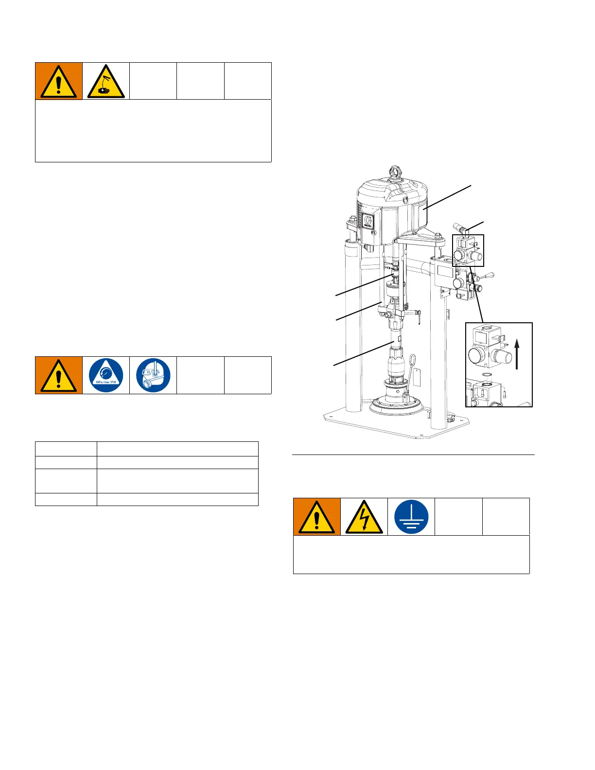
3. See Figure 10 and remove the pump coupling,
pump lower, and three tie rods from the air motor
supply system. Save these parts to be used when
installing the kit. Refer to the Supply Systems
Operation manual and the Supply Systems
Repair-Parts manual. See Related Manuals on
page 2.
4. Remove the air motor supply hose and fittings from
the top of the air controls.
5. On the air controls, disconnect the air motor shutoff
and control sections together by removing the two
screws underneath the air motor control as shown in
Figure 10. Lift the two sections to remove them.
Remove the o-ring from around the hole in the top of
the air controls.
6. Remove the air motor from the ram.
Assemble the Electric D60 Ram Conversion
Kit
NOTE: Refer to the Air to Electric D60 Ram
Conversion Kit, 25P280-82 parts on page 32 for
correct assembly.
1. Refer to Figure 11 on page 13 and remove the hex
nut from the mounting plate. Place the cable track
bracket (119) on the mounting plate and replace the
hex nut.
This conversion results in increased pressure to the
system. To help prevent serious injury from skin injec-
tion, all components downstream of the pump must
be rated to the new, higher maximum pressures. See
the Pressure Ratings table on page 4.
Kit Number Pump Lower Size
25P280 CM100
25P281
CM200, CM250, DF115, DF145,
DF180, DF220, DF290
25P282 CM500, DF430
FIG. 10: D60 with Air Motor
All electrical wiring must be done by a qualified elec-
trician and comply with all local codes and regula-
tions.
Air Motor
Air Motor
Air Supply
Fittings
Pump
Coupling
Tie Rods
Pump
Lower
Air Motor
Shutoff/
Control