Installation
3A6931A 25
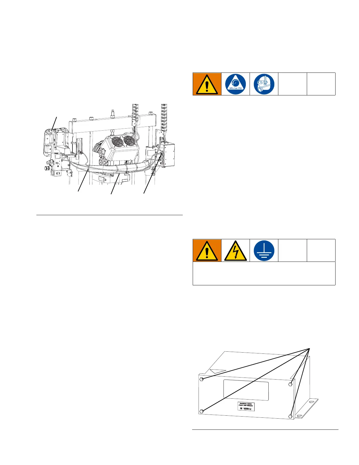
3. Route the CAN cable (502) along the back frame of
the ram. Use the six wire ties (503) to secure the
cable. See Figure 50. Coil any excess cable under
the ADM mounting bracket.
4. Connect the other end of the CAN cable (502) to the
bulkhead connection labeled C1 on the ram junction
box as shown in Figure 50.
5. Install the software as described in the E-Flo SP
Software Instructions. See Related Manuals on
page 2.
Standalone Pump Transformer
Kit
The pump transformer kit 25E268 is for pumps requiring
480 VAC power. Mount this transformer near the pump
in a secure location that prevents damage to the trans-
former or the wiring to the pump.
Mount the Pump Transformer
1. Follow the Pressure Relief Procedure for the air
motor pump and ram system you are using. See
Related Manuals on page 2.
2. Refer to the Transformer Mounting Hole Diagram
on page 45. Use the mounting holes as a guide to
drill holes for 1/4 in. (6 mm) screws.
3. Attach the transformer securely to the mounting sur-
face.
Connect the Pump Transformer Power
1. Follow the steps in Connect Power to the Electric
Pump System on page 10 before connecting power
to the transformer.
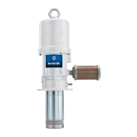
2. Remove the four screws on the transformer as
shown in Figure 51 and remove the front cover.
FIG. 50: Junction Box Connection for CAN Cable
All electrical wiring must be done by a qualified elec-
trician and comply with all local codes and regula-
tions.
FIG. 51: Pump Standalone Transformer