Installation
10 3A6931A
Assemble the Electric Pump Conversion
Kit
NOTE: Refer to the Air to Electric Pump Conversion
Kit, 25P277-79 parts on page 30 for correct assembly.
1. Use the shaft adapter (8,9) included in the kit and
connect the electric driver (1) to the pump coupling,
pump lower, and tie rods that were removed from
the air motor pump.
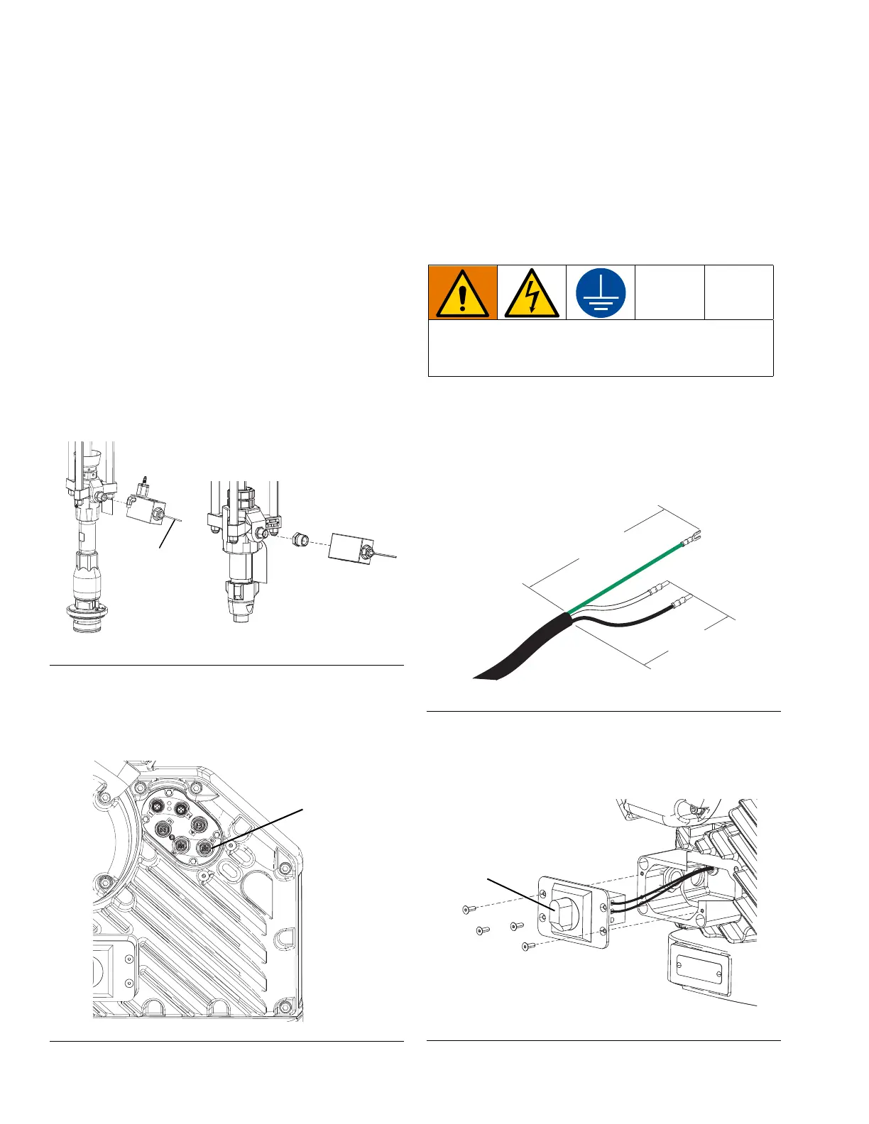
2. Connect the outlet check valve (2) using the adapter
fitting (4,5,6,7 depending on the kit). Apply thread
sealant to the threads of the check valve and the
adapter fitting prior to installation. Figure 2 shows
options for the 100 cc Check-Mate 100 pump and
the 115 cc Dura-Flo pump.
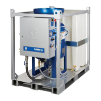
3. The pressure transducer cable from the outlet check
valve plugs into port 6 on the electric driver. See
Figure 3.
4. Use the wire ties (3) to secure the pressure
transducer cable to a tie rod.
5. Mount the electric pump as required for your system
configuration.
Connect Power to the Electric Pump
System
1. Cut power cord wires to the following lengths:
• Ground wire - 6.5 inches (16.5 cm)
• Power wires - 3.0 inches (7.6 cm)
• Add ferrules as necessary. See Figure 4.
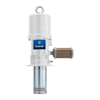
2. Remove the four screws to separate the junction
box cover and the disconnect switch from the junc-
tion box on the electric driver.
FIG. 2: Outlet Check Valve Options
FIG. 3: Electric Driver Ports
Dura-Flo 115
Check-Mate 100
Pressure
Transducer Cable
All electrical wiring must be done by a qualified elec-
trician and comply with all local codes and regula-
tions.
FIG. 4: Power Cord
FIG. 5: Remove Driver Junction Box Cover
LQ
LQ