Installation
3A6931A 11
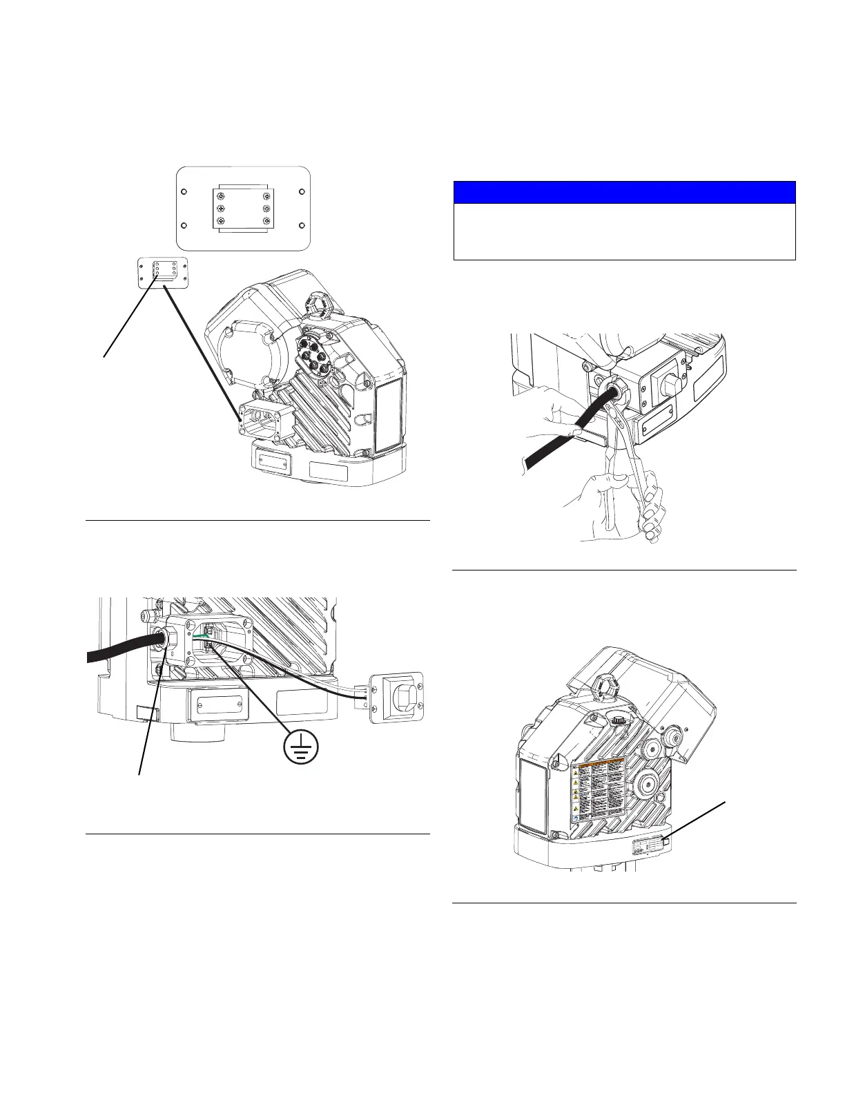
NOTE: Inside the junction box, power wires to the driver
are connected to terminals 3L2 and 5L3 on the discon-
nect block. Refer to Figure 6 for the terminal locations.
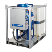
3. Insert the power cord through the cord grip and into
the driver junction box.
4. Refer to Figure 6 and connect the wires from the
power cord into terminals 4T2 and 6T3. Each wire
can be connected to either terminal.
5. Attach the ground wire to one of the two ground ter-
minals inside the junction box as shown in Figure 7.
NOTE: Do not attach the ground wire to the grounding
lug locknut located by the wiring cord grip on the outside
of the electric driver. The lug locknut should only be
used for other grounding purposes if needed.
6. Place the power wires into the open area on either
side of the disconnect block as space permits.
7. Reinstall the driver junction box cover and discon-
nect switch using the four screws removed in step 2.
8. Tighten the cord grip to securely hold the power
cord in the driver junction box.
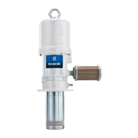
9. Place the identification label (16,17) included in the
kit on the electric driver as shown in Figure 9.
FIG. 6: Terminal Connections
FIG. 7: Connect Driver Junction Box Power
Incoming
Power
Power to
Driver
Disconnect
Block
For clarity, power wires to
the driver are not shown
Cord Grip
NOTICE
If wires get pinched when the screws are tightened,
damage will occur. Make sure all wires are routed
correctly before installation.
FIG. 8: Tighten Cord Grip
FIG. 9: Apply Label to Electric Driver
PART NO.
SERIES
SERIAL NO.
MAX FLUID WPR
MPa
bar
PSI
V
PH
A
HZ
See www.graco.com/patents
Artwork No.
294966 Rev. D