Clutch
WARNING
T
o reduce the risk of serious injury whenever you
are instructed to relieve pressure, always follow the
Pressure Relief Procedure
on page 6.
NOTE: The clutch assembly (4) includes the armature
(4a)
and rotor (4b). The armature and rotor must
be
replaced together so they wear evenly
.
NOTE: If the pinion assembly (19) is not yet separated
from
the clutch housing (2), follow Steps 1. to 4..
Otherwise,
start at Step 5..
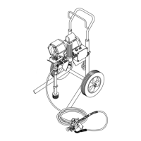
1.
Relieve the pressure.
2. Disconnect
the hose (59)
from the outlet nipple (49)
of
the displacement pump. Remove the spring clips
(100, 102) and bypass hose (101).
3. Remove the bottom two screws and lockwashers
(10, 11) from the back of the clutch housing (2) and
then remove the remaining three of screws and
lockwashers.
4. Tap lightly on the back of the bearing housing (21)
with
a plastic
mallet to loosen the assembly (D) from
the
clutch housing (2). Pull the assembly away
.
5. The armature (4a) will come with the assembly (D).
Remove the armature from the hub (19h)
6. Remove the four socket head capscrews (16) and
lockwashers (11).
7.
There are two ways to remove the rotor (4b).
a. Install
two of the screws in the threaded holes in
the
rotor
. Alternately
tighten the screws until the
rotor
comes of
f. See Fig. 25.
b. You can use a standard steering wheel puller.
However,
two 1/4–28 x 3 or 4 in. long screws (B)
are
also needed. Replace the short screws of the
steering wheel puller with the 3 or 4 in. long
screws. Turn the screws (B) into the threaded
holes
of the rotor (4b). T
ighten the capscrew
(C)
of
the
tool until the rotor comes of
f. See the Detail
in
Fig. 25.
8. Skip ahead to Reassembly, page 30, Step 7., or
continue
on the next page.
4b
11
16
4a
19
A
B
C
D
PINION
SHAFT
THREADED
HOLES
USING
A STEERING WHEEL
PULLER T
O REMOVE THE ROT
OR
11
10
49
2
59
100
101
102
21
Fig.
25