307-913
34
Displacement
Pump
424
411
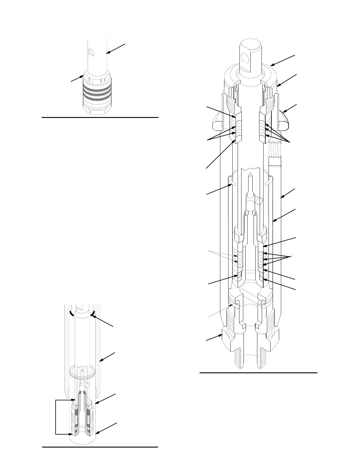
TORQUE
NUT
AGAINST ROD
T
O 27 N.m
DO NOT ALLOW NUT
(411)
T
O
MOVE WHEN IN
-
STALLING
PIST
ON ONT
O
ROD
Fig.
41
6. Use a wrench to CAREFULLY tighten the nut (411)
against
the piston rod to 25 N.m. See Fig. 41.
Use two wrenches to maintain the alignment men-
tioned
in Step 4., page 33.
7. Put
a new o–ring (417*) firmly in the cylinder groove.
See
Fig. 42.
8. One
at a time stack the male
gland (408*), alternate
the
packings (413*,
40 7*), and then install the female
gland (409*), into the top of the cylinder (419). See
Fig.
42.
9. Install
the packing
nut (416) and plug (405), but leave
loose
for now
. See Fig. 42.
NOTE: The
tapered end of the sleeve is the bottom of
it.
Do
not install it upside down. See Fig. 42.
10. Coat the piston rod and packings with oil. Carefully
slide the assembly INTO THE TOP OF THE
SLEEVE.
And
then slide the sleeve/piston rod assembly
INT
O
THE
BOTT
OM
OF THE CYLINDER
. This procedure
helps prevent damaging the packings during reas-
sembly.
See Fig. 42.
419
PISTON
ASSEMBLY
TAPERED
END
0030
418
417*
Fig.
42
TORQUE
T
O:
146 N.m
419
412*
POLY
LIPS MUST
F
ACE UP
413*
POLY
LIPS MUST
FACE
DOWN
410*
405*
*406
LEATHER
LIPS MUST
F
ACE UP
*403
U–CUP SEAL
LIPS MUST
FACE DOWN
415*
414*
*401
*408
*407
LEATHER
LIPS MUST
FACE DOWN
*409
*417
418
416
27
Fig.
43
11. Screw
down the cylinder locknut (27) until
it is finger
tight
at the bottom of the external cylinder threads.
12. Put
the flats
of the intake valve (423) in a vise. Install
a
new o-ring (401*) and screw the intake valve onto
the pump cylinder. See Fig. 42. Torque the valve to
146
N.m.
13.
Reinstall the pump. See page 32.