Pinion Assembly / Rotor / Field / Shaft / Clutch
14 308870G
Installation
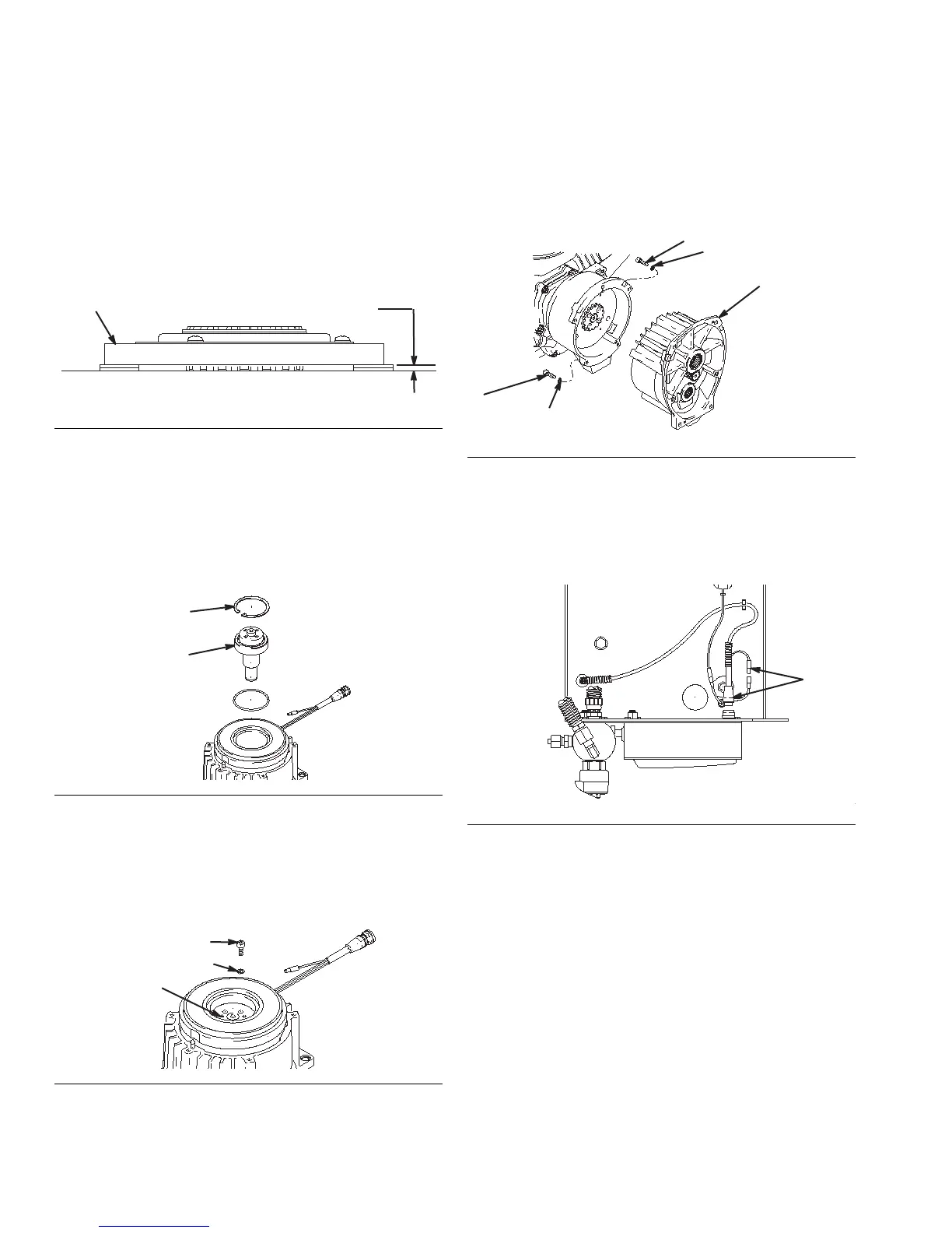
1. Lay two stacks of two dimes on smooth bench sur-
face.
2. Lay armature (4a) on two stacks of dimes (F
IG. 10).
3. Press center of clutch down on bench surface.
4. Install armature (4a) on engine drive shaft.
5. Install four screws (16) and lock washers (17) with
torque of 125 in-lb (14 N.m).
6. Tap pinion shaft (19d) in with plastic mallet (F
IG.
11).
7. Install retaining ring (19e) with beveled side facing
field.
8. Place pinion assembly on bench with rotor side up
(F
IG. 12).
9. Apply Locktite
®1
to screws. Install four screws (16)
and lock washers (17) (F
IG. 13). Alternately torque
screws to 125 in-lb (14 N.m) until rotor is secure.
Use threaded holes to hold rotor.
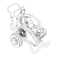
10. Install pinion assembly (19) with five screws (10)
and lock washers (9) (F
IG. 13).
11. Connect field cable (X) to pressure control and
engine lead (F
IG. 14).
FIG. 10
FIG. 11
FIG. 12
4a
87
0.12 +.01 in. (3.0 +.25 mm)
1.Locktite
®
is a registered trademark of Henkel.
FIG. 13
FIG. 14