Pinion Assembly / Rotor / Field / Shaft / Clutch
308870G 13
Pinion Assembly / Rotor / Field / Shaft / Clutch
Removal
If pinion assembly (19) is not removed from clutch hous-
ing (5), do 1. through 4. Otherwise, start at 5.
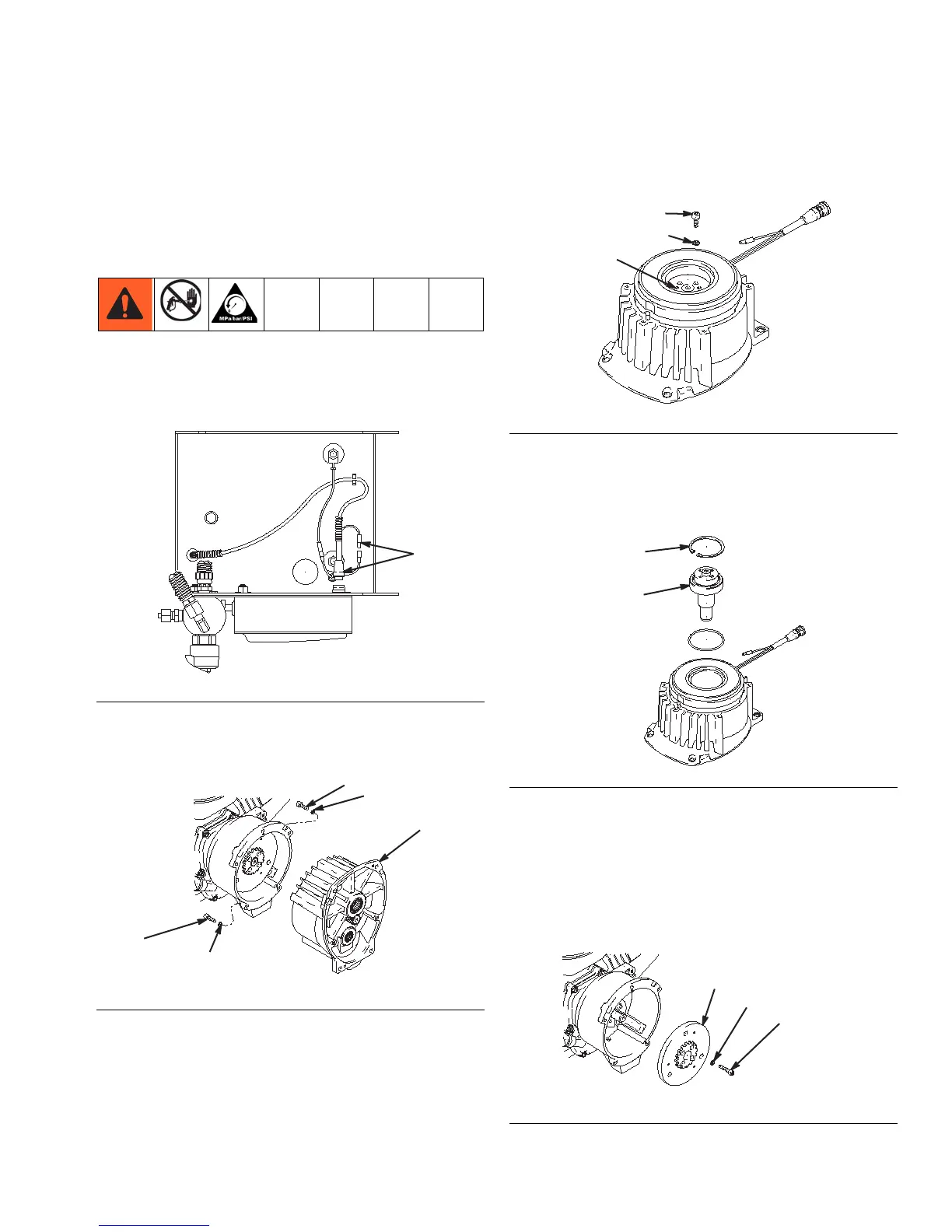
1. Relieve pressure, page 6.
2. Disconnect field cable (X) from pressure control and
engine lead (F
IG. 5).
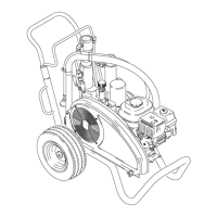
3. Remove five screws (26) and lock washers (17) and
pinion assembly (19) (F
IG. 6).
4. Place pinion assembly (19) on bench with rotor side
up.
5. Remove four screws (72) and lock washers (17).
Install two screws in threaded holes (E) in rotor.
Alternately tighten screws until rotor comes off (F
IG.
7).
6. Remove retaining ring (19e) (FIG. 8).
7. Tap pinion shaft (19d) out with plastic mallet (F
IG.
8).
8. Use an impact wrench or wedge something
between armature (4a) and clutch housing to hold
engine shaft during removal (F
IG. 9).
9. Remove four screws (16) and lock washers (17)
(F
IG. 9).
10. Remove armature (4a) (F
IG. 9).
FIG. 5
FIG. 6
FIG. 7
FIG. 8
FIG. 9