Setup
313997ZAA 41
7. Connect heated hose monitor zones
NOTE: For Heated HFR models only, see Heated Hose
manual for detailed instructions on connecting heated
hoses.
a. Turn main power OFF .
b. For Heated HFR Models only, assemble
heated hose sections, FTS, and whip hose. See
Heated Hose manual 3A0237 for heated hose
connection details and illustrations for the vari
ous types of heated hoses.
For Non-Heated HFR Models only, assemble
fluid supply hose sections and whip hose.
c. Connect A (Red) and B (Blue) hoses to A (Red)
and B (Blue) outlets on HFR fluid manifold (FM).
Hoses are color coded: red for component A,
blue for component B. Fittings are sized to pre
vent connection errors.
NOTE: Gun fluid manifold hose adapters allow use of
1/4 in. and 3/8 in. ID fluid hoses. To use 1/2 in. (13 mm)
ID fluid hoses, remove adapters from gun fluid manifold
and install as needed to connect hose.
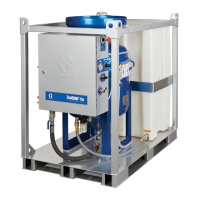
d. For Heated HFR Models only, connect
cables (Y). Connect electrical connectors (V).
Be sure cables have slack when hose bends.
Wrap cable and electrical connections with
electrical tape. See Heated Hose manual for
heated hose connection details and illustrations
for the various types of heated hoses.
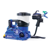
8. For systems with a gun fluid manifold, close gun
fluid manifold valves A (Red) and B (blue).
NOTICE
For Heated HFR models only, the FTS (C) and
whip hose (D) must be used with heated hose. See
step 6 on page 40 for FTS installation. Hose length,
including whip hose, must be 10 ft (3 m) minimum.