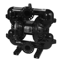
Installation
Air Air
Air
Line Line
Line
Models Models
Models
that that
that
Include Include
Include
a a
a
Compressor: Compressor:
Compressor:
Anairlineisalreadyconnectedfromthecompressor
tothepumpairinlet.
Using Using
Using
Your Your
Your
Own Own
Own
Compressor: Compressor:
Compressor:
Installagrounded,exibleairhosefromthe
compressortothepumpairinlet(E).
Using Using
Using
Shop Shop
Shop
Air: Air:
Air:
1.Installanairlter/regulatorassembly(H).The
uidstallpressurewillbethesameasthesetting
oftheairregulator.Thelterremovesharmful
dirtandmoisturefromthecompressedairsupply.
2.Locateableed-typemasterairvalve(G)closeto
thepumpanduseittorelievetrappedair.Be
surethevalveiseasilyaccessiblefromthepump
andlocateddownstreamfromtheregulator.
Trappedaircancausethepumptocycle
unexpectedly,whichcouldresultinserious
injuryfromsplashing.
3.Locateanothermasterairvalve(J)upstream
fromallairlineaccessoriesanduseittoisolate
themduringcleaningandrepair.
4.Installagrounded,exibleairhose(F)between
theaccessoriesandthepumpairinlet.
Fluid Fluid
Fluid
Supply Supply
Supply
Line Line
Line
1.Connectagrounded,exibleuidhose(K)to
theuidinletport.Theportonpumpswith
aluminum,stainlesssteel,orcastironuid
sectionsis2innpt(f)or2in..bspt.Onpumps
withpolypropylene,conductivepolypropylene,
orPVDFuidsections,theportisa2in.raised
faceANSI/DINange.
2.Iftheinletuidpressuretothepumpismore
than25%oftheoutletworkingpressure,the
ballcheckvalveswillnotclosefastenough,
resultingininefcientpumpoperation.Excessive
inletuidpressurealsowillshortendiaphragm
life.Approximately3–5psi(0.02–0.03MPa,
0.21–0.34bar)shouldbeadequateformost
materials.
3.Formaximumsuctionlift(wetanddry),see
TechnicalData,page38.Forbestresults,always
installthepumpascloseaspossibletothe
materialsource.Minimizesuctionrequirements
tomaximizepumpperformance.
Fluid Fluid
Fluid
Outlet Outlet
Outlet
Line Line
Line
1.Connectagrounded,exibleuidhose(N)to
theuidinletport.Theportonpumpswith
aluminum,stainlesssteel,orcastironuid
sectionsis2in.npt(f)or2in.bspt.Onpumps
withpolypropylene,conductivepolypropylene,
orPVDFuidsections,theportisa2in.raised
faceANSI/DINange.
2.Installauiddrainvalve(L)neartheuidoutlet.
3.Installashutoffvalve(M)intheuidoutletline.
14
3A4068H
 Loading...


