16 308573
Service
Tools Required
•
Torque wrench
• 9/16 in. socket wrench
• O-ring pick
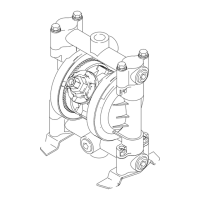
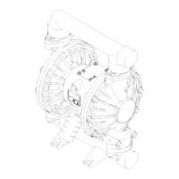
Ball Check Valves
NOTE: Fluid Section Repair Kit D05277 is available. Kit
parts are marked with an asterisk, for example (301*).
Use all the parts in the kit for the best results. Always
replace the o-rings (139*) with new ones whenever they
are removed for any reason.
1. Relieve the pressure. Disconnect all hoses.
2. Remove the pump from its mounting.
3. Unscrew the four bolts (105), washers (107), and nuts
(106) holding the top manifold (102) to the covers
(101). Lift the manifold off the pump. See Fig. 9.
4. Remove the outer o-ring (139*), ball stop (202*), ball
(301*), ball guide (201*), and inner o-ring (139*) from
each of the covers (101).
5. Turn the pump over. Remove the bolts (105), nuts
(106), feet (108) and bottom manifold (102).
6. Remove the outer o-ring (139*), ball guide (201*), ball
(301*), ball stop (202*), and inner o-ring (139*) from
each of the covers (101).
7. Clean all parts. Inspect parts and replace worn or
damaged ones.
8. Reassemble. Follow all notes in Fig. 9. Be sure the
ball checks are assembled exactly as shown.
Fig. 9
WARNING
To reduce the risk of serious injury whenever you are
instructed to relieve pressure, always follow the
Pressure Relief Procedure on page 10.
9256A
101
105
105
106
106
107
102
102
1
1
1
*139
*201
*202
*139
*301
*139
*201
*202
*139
*301
Torque to 80 to 90 in-lb (9 to 10 N•m). See
Torque Sequence, page 22.

 Loading...