6 308573
Installation
Example of a Gear Oil Receiver Evacuation System
Fig. 2
Fig. 3
9249A
H
A
C
D
G
J
L
Y
F
B
E
J
J
J
J
J
J
K
K
K
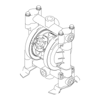
KEY
A Pump air regulator
B Air line quick coupler (required)
C Fluid drain valve (required)
D Control valve
E Suction wand
F Suction hose
G Fluid quick coupler
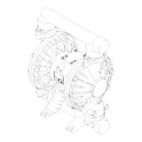
H Husky 716 pump
J Electrically conductive, bonded air
supply line
K Electrically conductive, bonded fluid
line to pump
L Electrically conductive, bonded
wasteoil linetostorage tank
Y Ground wire (required; See page 4
for installation instructions. Pump
must be properly grounded and
entire system electrically bonded.)
Bay 1
Bay 2
Bay 3
9250A
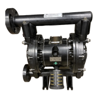
Example of a Waste Oil Evacuation
System, or General Fluid Transfer
Application
Shown with fluid inlet and outlet ports facing
forward (see page 8).
NOTE: Air inlet restrictor may be removed
for higher flow capabilities.
KEY
A Pump air regulator
B Air line quick coupler (required)
C Fluid drain valve (required)
D Wall-mount bracket (Part No. 224835)
F Electrically conductive suction hose
G Fluid quick coupler
H Husky 716 pump
J Electrically conductive, bonded air supply line
L Electrically conductive, bonded waste oil line to storage
tank M Waste oil receiver
S 90° Elbow (required for wall mount applications)
Y Ground wire (required; See page 4 for installation
instructions. Pump must be properly grounded and
entire system electrically bonded.)

 Loading...