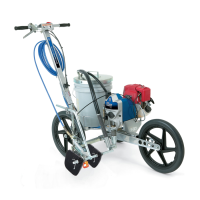
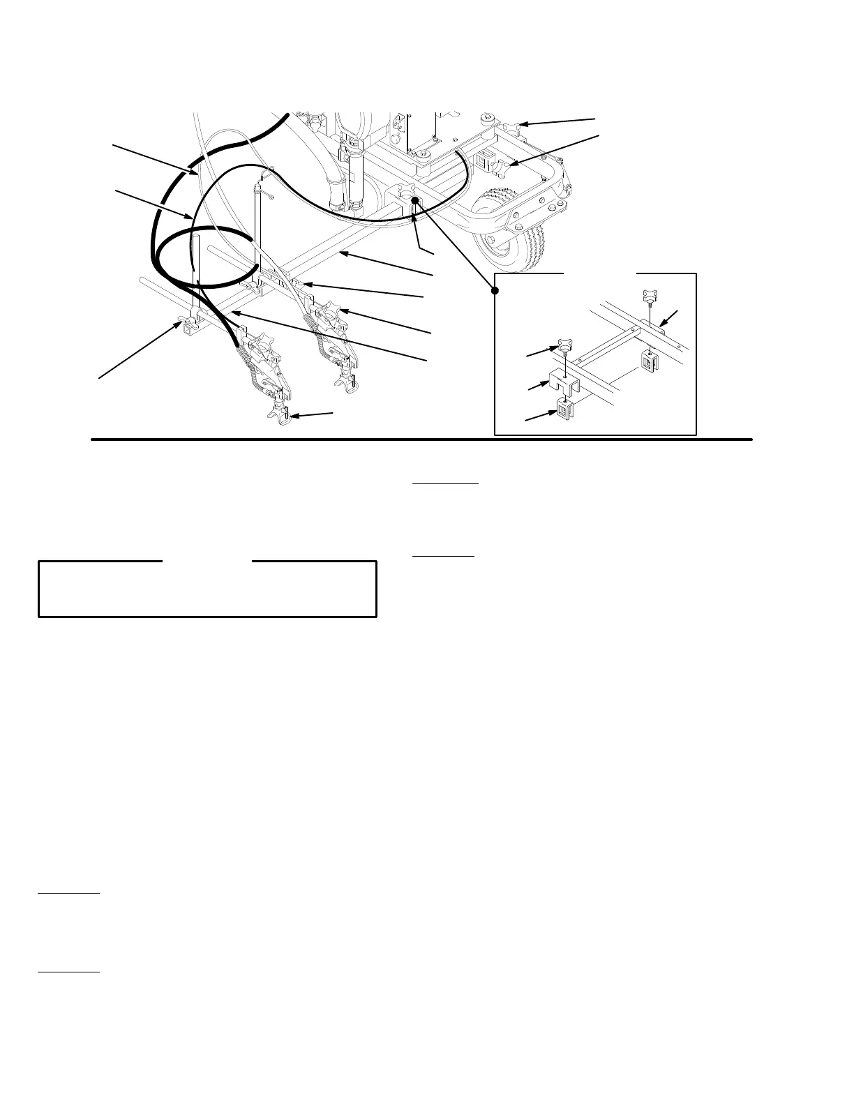
Positioning
the Gun Arm Assembly
Fig.
13
02158
D
93
405B
405A
404
6
ENGINE SIDE
PUMP SIDE
B
“WINGS”
OF TIP GUARD
B
E
A
D
DETAIL
A
1
402
4
The
gun arms can be positioned
for a variety of spraying
needs.
The drawings on page 20 primarily show the guns
mounted on the pump side of the Linestriper . However,
one
or both guns may be mounted on the engine side.
Whenever
Y
ou Move the Guns
CAUTION
Do not kink the cables, which could prevent them
from
properly triggering and untriggering the guns.
Disengage
the trigger cables and engage the gun trigger
safety latch first. See page 22. Do not kink the trigger
cables.
Pull out more of the 50 ft. hose, if necessary
.
After moving the
guns, reposition the spray tip guard so
it is parallel to the ground and its “wings” face the front
and back of the unit. Disengage the gun trigger safety
latch
and engage the trigger cable.
V
ertical Position of
the First or Second Gun
Loosen
the arm clamp (6) and move the gun
up or down.
Tighten
the clamp. Engage the trigger cable.
Horizontal Position of the First Gun
Method 1: Disengage the trigger cable. Loosen the car-
riage clamps (B,D) and slide the carriage bar (4) left or
right,
so the gun will be outside the tire path. T
ighten
the
clamps.
Engage the trigger cable.
Method 2: Disengage the trigger cable. Loosen the arm
clamp
(6) and rotate the gun out to the side. T
ighten the
bolt.
Engage the trigger cable.
NOTE: Use
methods 1 and 2 together to obtain the max
-
imum
distance of one gun from
the unit, which is helpful
when
spraying around obstacles.
Horizontal Position of the Second Gun
Method 1: Disengage the trigger cable. Loosen the
clamps (405A, 405B). Slide the second gun bar (404)
horizontally,
being sure both clamps
engage the second
gun bar. T
ighten the clamps. Engage the trigger cable.
Method 2: Disengage the trigger cable. Loosen the arm
clamp
(6) and rotate the gun out to the side. T
ighten the
bolt.
Engage the trigger cable.
NOTE: Use
methods 1 and 2 together to obtain the max
-
imum distance of 33–
1
/
2
in. (851 mm) between the center
of
two guns.
Mount
Guns on the Engine Side of the Cart
1. For both guns, disengage the trigger cable and en-
gage
the trigger safety latch. See page 22.
2. Loosen the gun holder knobs (93) and remove the
gun.
Lay the guns out of the way
.
3. Remove the knobs (E) on both carriage clamps
(B,D);
the carriage bar (4) and extension clamps (A)
will
drop down. See Fig. 13
, DET
AIL A.
4. Lift
the front tire and rotate the carriage
bar 180
un
-
der
the cart and to the other side of it.
5. Position
the carriage bar below the carriage
clamps
(B,D). Align the holes in the top of the extension
clamps
(A) with the holes in the
carriage bar clamps
and
install the knobs (E). See Fig. 13
, DET
AIL A.
6. Loosen
the post/arm clamps (5) and rotate the
guns
forward.
Retighten the clamps.
7. Install the guns. Note to which gun and position on
the
dual gun selector each of the cables (1 and 402)
goes. Route the hoses and cables carefully to pre-
vent kinking. Position the spray tip guards. Disen-
gage
the gun trigger safety latches.
Engage the trig
-
ger
cables.
 Loading...