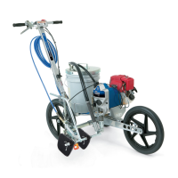
Caster
Lever and Cable Operation
The AccuT rack caster is factory–adjusted to
track
in a straight line. It should not require adjust
-
ment
unless it is replaced. If a line is tracking poorly
,
check for the following items before aligning the
caster.
1. Even
back tire pressure.
2. Even tension on the rear tire bearings (adjust
nuts
(10) as needed). See page 42.
3. Even tightness of caster setscrews (F). See
Fig.
16.
4.
Uneven painting surface.
5.
Operator technique.
CAUTION
Operation
The
normal operating mode of the
AccuT
rack
caster is
locked
in the straight forward position.
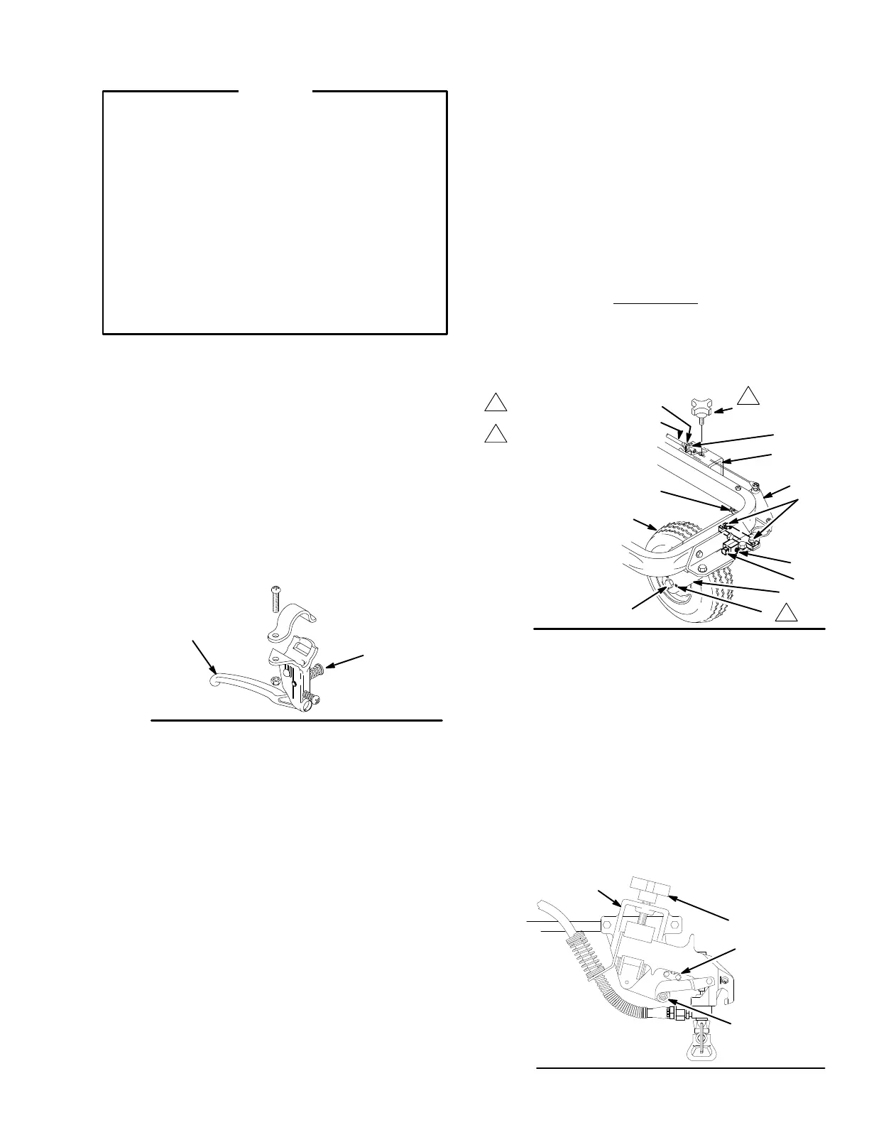
1. For
a free moving caster:
Squeeze and hold the cast
-
er lever (22).
2. To lock the caster in the free moving position,
squeeze
the trigger
, push in and hold the the
button
(A)
and release the trigger
. See Fig. 15.
3. T
o return to the normal mode, squeeze and release
the
caster lever and move the Line
Lazer forward to
lock
the caster in the straight position.
22
A
0018
Fig. 15
Maintenance
See Fig. 16
Paint builds up on the caster triggering mechanism. T o
keep
it operating properly
, use a grease gun at the grease
zerks (32A, 32B) to flush out the buildup – two to four
times
a month, depending on use.
Caster Tire Replacement
See Fig. 16.
Remove the setscrews (F) from the caster fork (E). Re-
move screw (G) and the tire (1 14a). Install the new tire
and
the setscrews (F). T
ighten the
setscrews equally so
the
tire has no play in it, but turns freely
.
Caster Cable Tension Adjustment See Fig.
16.
1. Loosen the nut (A) located just outside the carriage
clamp
(B).
2. With
the pin (D) fully engaged
in the
caster fork (E),
pull
back on the cable (2) to increase the cable ten
-
sion,
or push it forward to reduce the tension. Finger
tighten
the nut (H). T
ighten the nut (A) firmly
.
Shown
removed only
for visual purposes
A
2
B
87
32A
32B
D
D
114a
E
F
T
ighten equally so tire
has no play in it but
turns freely
G
H
0019
Fig.
16
1
2
1
2
Caster Alignment
Do this adjustment only if the caster or tire is replaced,
or
if no other solutions to poor tracking are found.
1. Loosen
the two capscrews (87), grasp the tire visual
-
ly
align the tire. T
ighten the
capscrews evenly
. Move
the unit forward. If the caster appears straight, start
the unit (use water) and spray along a true straight
line.
Continue adjusting as necessary
. See Fig. 16.
How
T
o Mount the Gun
1. Relieve
pressure. See page 4.
2. Disengage the trigger cable. See page 22. Engage
the
gun’
s trigger safety latch (B).
3.
Loosen the gun holder knob (93).
4. Position the gun so the gun trigger is resting on the
remote
trigger lever (A).
5. Be sure that the gun is mounted straight and then
tighten
the knob (93) firmly
.
6. Disengage
the gun safety latch. Engage the remote
trigger
cable. See page 22.
93
95
A
B
Fig. 17
0020B
 Loading...