How
to install cable
Correctly installed cable
122
F
99
402
34
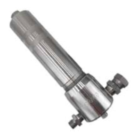
DETAIL
B
402
DET
AIL A
Torque
to 15 in–lb
(1.7 N.m) then back of
f
1/16 to 1/8 turn
0010
0011
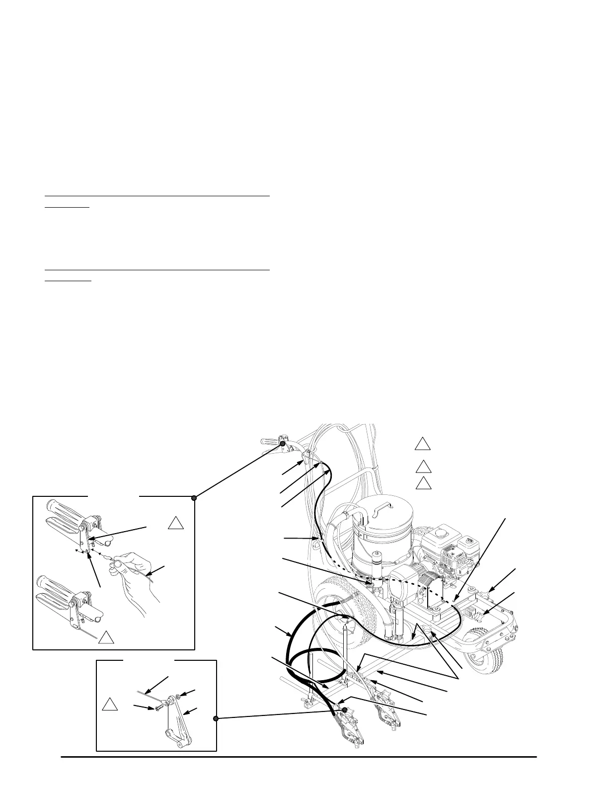
Fig.
5
1
1
3
2
2
3
02157
48
C
405A
4
27,104
7
404
405B
14
402
403
D
E
A
B
401
94
Second
Gun and Hose Installation
NOTE:
Fig. 5
represents the installation at Step 3.
NOTE:
T
o switch the gun
assemblies to the engine side
of
the cart, refer to the instructions on page 18 before in
-
stalling
the second gun kit.
1. Disengage
the trigger
cable from the block (48) of the
unit’s existing gun. See page 22. Engage the gun’ s
trigger
safety latch.
2. Loosen
the carriage clamps (B, C). Slide the
carriage
bar (4) of
f the cart.
3.
For mounting the second gun bar on the pump side
of
the
cart:
Slide a clamp (405A) onto the carriage bar
(4). Slide the carriage bar through the pump-side car
-
riage clamp (B) and into the center of the cart. Now
slide another clamp (405B) onto the carriage bar .
See
Fig.
55.
For
mounting the second gun bar on the engine side
of
the cart:
Follow Step 3, except slide the carriage
bar through the engine-side carriage clamp (C) and
the into the center of the cart. The knobs of the
clamps (405A, 405B) must face back toward the
handle
bars.
4. Slide
the carriage bar (4)
through to the opposite car
-
riage
clamp. T
ighten the carriage clamps (B,C).
5. Slide the second gun bar (404) far enough into the
carriage
bar that the clamp (405B) engages the bar
.
Position the clamps (405A, 405B) over the notches
(A)
in the carriage bar (4) and tighten the clamps.
NOTE:
For stable gun operation, the second
gun bar (404) has a maximum recommended
extension from the carriage bar of about
11-
1
/
4
” (286 mm).
6. Disconnect
the trigger cable from the second gun at
the
screw (34). See Fig. 5
, DET
AIL B.
7. Unscrew the filter ’s second outlet cap (14). Screw
the
short hose (403) onto the filter nipple.
8.
Remove the guide clamp screw (27).
9. Snap
the cable bushing (E) into the guide plate (D).
Route the trigger cable (402) parallel with the main
gun
cable, separating the guide clamp (104) to feed
the cable through it. Install and tighten the clamp
screw
(27). Route the cable through the cable guide
(7)
and to the second gun.
10. Slide
the hooked end of the cable (402) through
the
hole
(F) in the lever plate (122). Rotate and slide the
hook
back until it engages the plate. See DET
AIL A.
11. Reconnect the trigger cable to the second gun at
screw (34). Torque the screw to 15 in–lb (1.7 N.m),
back it off 1/16 to 1/8 turn and then tighten the jam
nut (99) while holding the screw (34). Be sure the
plate
(94) moves freely
.
12. Install
the clip (401) to hold the cable onto the frame.
13. Connect
both trigger cables to the
blocks (48). Then
adjust
the cable tension. See pages 21 and 22.
14. Do
not
install the spray tip until the system is primed.
15. Adjust
simultaneous gun triggering. See page 19.
 Loading...