34
308-105
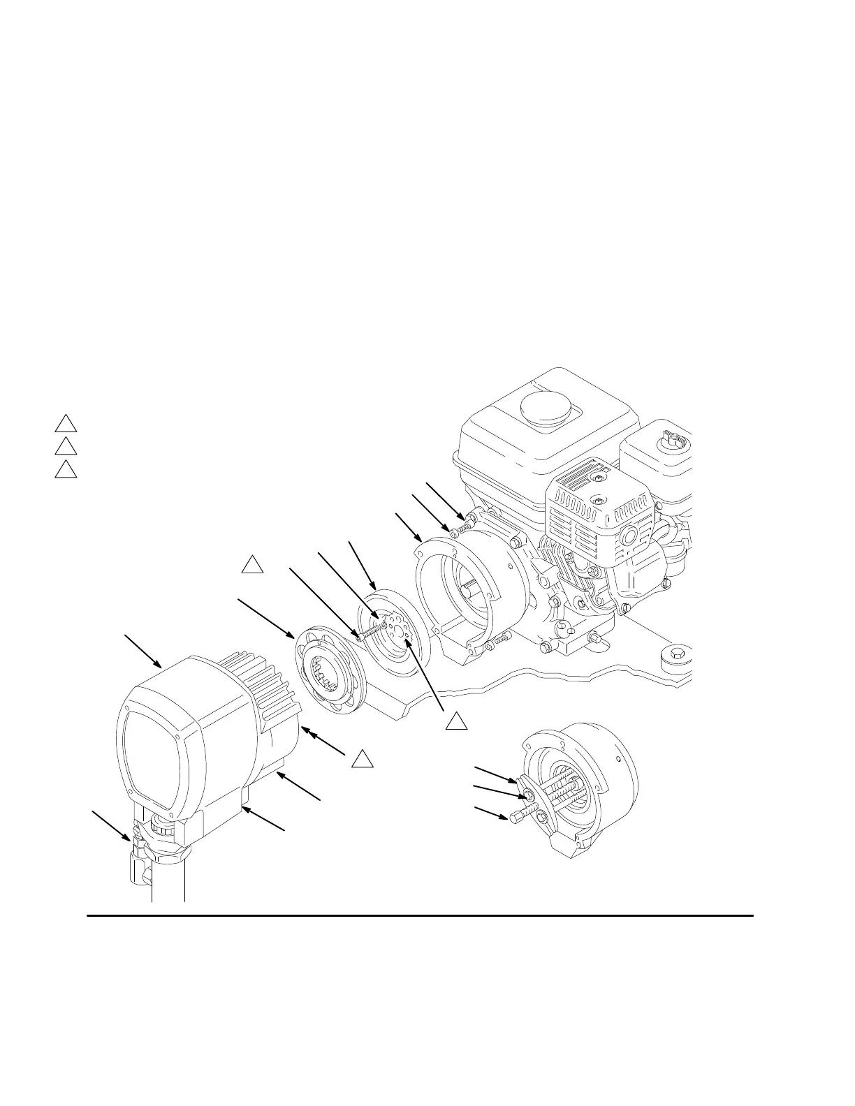
Clutch
NOTE: The clutch assembly (55) includes the armature
(55a)
and
rotor (55b). The armature and rotor must be re
-
placed
together so they wear evenly
.
NOTE:
If the pinion assembly (138) is not yet separated
from the clutch housing, follow Steps 1 to 4. Otherwise,
start
at Step 5.
1. Follow
the
Pressure Relief Procedure W
arning
on
page
4.
2. Disconnect the hose (133) from the displacement
pump.
3. Remove
the
bottom two screws (67) from the clutch
housing (61) and then remove the remaining three
screws (67).
4. Tap lightly on the back of the bearing housing (77)
with
a plastic
mallet to loosen the assembly (D) from
the clutch housing (61). Pull the assembly away; the
armature
(55a) will come with it.
5.
Remove the armature from the pinion shaft.
6. Remove the four socket head capscrews (157) and
lockwashers (156). Install two of the screws in the
threaded
holes in the rotor (55b). Alternately
tighten
the
screws until the rotor comes of
f. See Fig. 38.
7. Skip
ahead to
Reassembly
,
page 39, Step 6, or con
-
tinue
on the next page.
Fig. 38
A
B
C
D
55a
157
156
55b
61
59
67
Torque
to 7 ft–lb (9.5 N.m)
Use a steering wheel
puller to remove rotor
77
138
133
1
3
2
1
2
Pinion shaft
Threaded holes
3
 Loading...