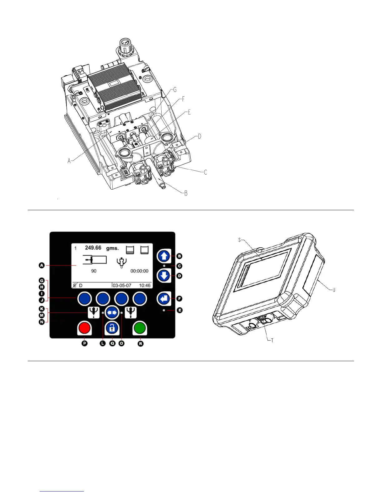
Component Identification
Key:
A Drive Block
B Hydracheck (optional)
C Check Valve
D Cylinder (Metering Tube)
E Rear Bearing
F Phase Adjustment Screw/Locking
Nut
G Mounting Hole in Base Frame
Figure 4: PR70 Top View with Shield, Tanks, DV and HMI Removed.
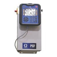
HMI Control and Indicators
Figure 5: PR70 HMI Controls
Key:
A Screen, Display Area
B, D Up and Down Keys
C Up and Down Key LED
E Enter Key LED
F Enter Key
G-J Soft Keys 1 thru 4 (Left to Right).
K Shot Mode ICON
L Shot Mode LED
M Mode Select Key
N Operator Mode ICON
O Operator Mode LED
P Red Stop or Cancel Key (used to stop machine
operation)
Q Lock Key (used to enter and exit setup screens)
R Green Go Key (used to request a shot)
S Display area
T Diagnostic LED’s
U HMI Rear Access Panel (used to access clock
battery and for reprogramming the HMI).
312393C 12 of 52