EasyManua.ls Logo

Graco PR70 Series User Manual

Graco PR70 Series
52 pages
To Next Page IconTo Next Page
Page #1 background imageLoading...
Page #1 background image
Operation and Maintenance
PR70
TM
2 Component
Liquid Dispensing Systems
312393C
PR70 All Models
100 PSI (0.7 Mpa, 7 bar) Maximum Air Inlet Pressure
For Dispensing Multi-part Sealants and Adhesives
Not Designed for Use in Explosive Atmospheres
Important Safety
Instructions
Read all warnings and
instructions in this
manual.
PROVEN QUALITY, LEADING TECHNOLOGY.
GRACO OHIO INC.
8400 PORT JACKSON AVE. NW, NORTH CANTON, OH 44720-5464
Phone: 330.966.3000 Fax: 330.966.3006
www.liquidcontrol.com
LiquidControlService@graco.com LiquidControlParts@graco.com
Copyright 2007, Graco Inc is a registered to I.S. EN ISO 9001
Table of Contents

Questions and Answers:

Graco PR70 Series Specifications

General IconGeneral
Power SupplyPneumatic
Air Inlet Pressure0.5 - 0.7 MPa (5 - 7 bar, 70 - 100 psi)
Wetted PartsStainless Steel, PTFE, UHMWPE
Viscosity RangeUp to 1, 000, 000 cps
Pump TypePositive displacement
Ratio Range1:1 to 10:1
Dispensing CapacityVariable, depending on configuration
DimensionsVariable, depending on configuration

Summary

Models

2007 Product Configurator - PR70

Describes the system's configurable options and part numbering.

Safety Warnings

Electric Shock Hazard

Details electrical safety risks and necessary precautions.

Skin Injection Hazard

Explains the danger of high-pressure fluid injection.

Toxic Fluid or Fumes Hazard

Covers risks associated with hazardous materials.

Fire and Explosion Hazard

Outlines precautions for flammable environments.

Equipment Misuse Hazard

Warns against improper operation and modifications.

Moving Parts Hazard

Highlights dangers from mechanical movement.

Personal Protective Equipment (PPE)

Recommends safety gear for operators.

HMI Operation and Controls

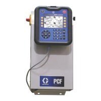
HMI Control Panel Layout

Describes the physical controls and display of the HMI.

HMI Control Key and Functions

Explains the purpose of each button and indicator.

Run Screen Operations

Screen Navigation Diagram

PR70 HMI Navigation Flow

Visual guide showing the sequence between HMI screens.

Priming and Calibration

Piston Position Calibration (C1)

Calibrating piston travel limits for accurate dispensing.

Phasing Calibration (C2)

Adjusting material flow for proper mixing ratio.

Machine Calibration Shots (C4)

Performing shots to calibrate dispensing volume.

Password Management

Procedures and Error Handling

Pressure Relief Procedure

Safely depressurizing the system.

Error Code Reporting

How the machine indicates and displays faults.

Error Code Reference Table

Comprehensive list of error codes, causes, and solutions.

ICON Reference Tables

Maintenance and Software Updates

Troubleshooting Guide

Troubleshooting Common Issues

A guide to diagnosing and resolving operational problems.

Wiring Diagrams

PR70 Wiring Interconnect Diagram

Illustration of electrical connections between system modules.

Detailed PR70 Wiring Diagram

Comprehensive schematic of electrical pathways.

Technical Specifications

PR70 Technical Data Summary

Key performance, operational, and environmental specifications.

Physical Dimensions

Related product manuals