EasyManua.ls Logo

Graco PrecisionSwirl User Manual

Graco PrecisionSwirl
150 pages
To Next Page IconTo Next Page
Page #1 background imageLoading...
Page #1 background image
3A2098S
Instructions - Parts
PCF
with
PrecisionSwirl
Precision Dispense System
Electronically-controlled fluid metering system that provides precise continuous flow of
up to four single-component sealants and adhesives through closed-loop technology.
Not for use in explosive atmospheres or hazardous locations.
For professional use only.
See page 4 for model information. See page 5 for
maximum working pressure and approvals.
IMPORTANT:
This manual does not apply to some PCF sys-
tems. See note on page 3 to verify this is the
correct manual for your PCF system.
Important Safety Instructions
Read all warnings and instructions in this
manual. Save these instructions.
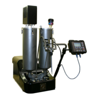
Optional PrecisionSwirl Orbital
Dispenser (sold separately)
PCF Control Center
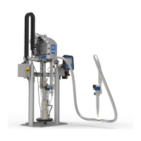
PCF Fluid Plate
EN
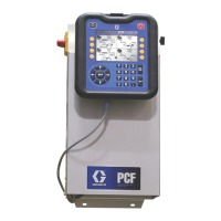
Table of Contents

Questions and Answers:

Graco PrecisionSwirl Specifications

General IconGeneral
BrandGraco
ModelPrecisionSwirl
CategoryDispenser
LanguageEnglish

Summary

Warnings

Electric Shock Hazard

Precautions against electrical shock during operation and servicing.

Skin Injection Hazard

Risks of high-pressure fluid injection and required immediate treatment.

Fire and Explosion Hazard

Measures to prevent fire and explosion in areas with flammable fumes.

Equipment Misuse Hazard

Consequences of misusing the equipment and operating under adverse conditions.

Burn Hazard

Warning about hot surfaces and fluids during operation.

Toxic Fluid or Fumes Hazard

Risks associated with toxic fluids or fumes and necessary precautions.

Personal Protective Equipment

Required protective gear for operating and servicing the equipment.

System Configurations

Advanced Display Module (ADM)

Automation Gateway Module

Installation

Before Installation

Preparatory steps and documentation required before system installation.

Installation Steps

A step-by-step guide to installing the PCF system components.

Install Control Center

Mount

Criteria and dimensions for mounting the PCF control center and expansion enclosures.

Electrical Connections

Install Fluid Plate Assemblies

Mount Assembly

Steps and considerations for mounting the fluid plate assembly to automation units.

Mount Coriolis Flow Meter

Ground

Connect Fluid and Air Lines

Install Cable Assemblies

Install Gateway Module Interface

Discrete Gateway Module

System Setup

Overview

Explains the PCF system setup process and required steps for operation.

Configure System

Setting up the number of installed fluid plates and swirl dispensers.

Configure Control Settings

Configure Mode Settings

Configure Delay Settings

Configure Flow Meter Settings

Configure Pressure Loop Settings

Adjust Pressure Sensors

Configure Errors

Setup Maintenance Schedule/Parameters

On/Off Delays

Operation

Startup

Procedures for initial and standard startup of the PCF system.

Load Material

Steps to load system material and prepare for dispensing.

Maintenance Mode Operation

Verify System Operation

Dispense from Each Valve

Verify Flow Meter Calibration

Manually Adjust Control Loop Parameters

Dispense From Maintenance Screen

Automation Control (Normal Operation)

Jobs

Explains jobs, styles, and how the PCF system operates during automation control.

Styles

Precharge Modes

Typical Job Cycle

Typical Job Cycle Chart

Pressure Relief Procedure

Shutdown

USB Data

Troubleshooting

Fluid Plates

Common problems and solutions for fluid plate issues like no outlet pressure.

Flow Meter

Fluid Regulator

Dispense Valves

Swirl Dispenser

Gateway Module

LED Diagnostic Information

Errors

View Errors

How to view and acknowledge system errors, alarms, deviations, and advisories.

Fluid Plate Events and Errors

Troubleshooting for swirl motor faults and maintenance due to orbiter usage.

Diagnose Errors

Guidance on diagnosing errors using event codes and troubleshooting tables.

Event and Error Codes and Troubleshooting

System Events and Errors

List of system events, their types, causes, and solutions.

Control Center Events and Errors

Troubleshooting for control center events like USB disabled or gateway errors.

Fluid Plate Events and Errors

Swirl Events and Errors

Maintenance

Mechanical

Recommended daily, weekly, and monthly mechanical maintenance tasks.

Electrical

Recommended weekly electrical maintenance tasks for system reliability.

Advanced Display Module (ADM)

Upgrade Gateway Module Software (16K743)

Upgrade Gateway Module Fieldbus Map (16N601 or 17P799)

Upgrade Fluid Control Module (FCM) Software (16K743)

Repair

Fluid Plate Assembly

Describes how to remove and replace components on the fluid plate assembly.

Remove Flow Meter from Mounting Plate

Steps to disconnect and remove the flow meter from its mounting plate.

Install Flow Meter on Mounting Plate

Replace Fluid Control Module

Repair Fluid Regulator

Replace Amplifier

Adjust Amplifier Settings

Control Center Assembly

Prepare Control Center for Repair

Steps to prepare the control center for repair by powering off and disconnecting.

Replace Gateway Module

Procedure for replacing the Gateway module and upgrading software.

Replace Advanced Display Module

Appendix A - Advanced Display Module (ADM)

Display Overview

Overview of the ADM display, divided into Setup Mode and Run Mode functions.

Setup Mode

Navigating through the PCF setup mode screens for system configuration.

Automation Gateway Setup Screens

Screens for setting up and viewing information for automation Gateway modules.

Discrete Gateway (Automation) Setup Screen

Setting active errors and selecting command value type (Analog or Digital).

Fluid Plate x, Screen 3 (Delay Settings)

Setting on and off delays for valves and the regulator in milliseconds.

Fluid Plate x, Screen 6 (Error Type)

Defining error types (alarm, deviation, none) for pressure, flow, volume, and target deviations.

Fluid Plate x, Screen 8 (Style)

Setting up styles, including style number, name, target volume, and tolerances.

Setup Mode Functions

User functions available in Setup Mode for configuring system components and settings.

Advanced Setup Screens

Screens for setting units, formats, USB settings, and software information.

Fluid Plate x, Screen 4 (Control Loop and Flowmeter Settings)

Configuring meter type, K-Factor, and pressure/bead control loop parameters.

Fluid Plate x, Screen 7 (Maintenance Advisory Limits)

Setting volume or hour limits to trigger maintenance advisories for system components.

Fluid Plate x, Screen 9 (Swirl Association)

Associating swirl dispensers with fluid plates and handling swirl errors.

Run Mode Functions

User functions available in Run Mode for monitoring and adjusting system operations.

Fluid Plate x, Screen 5 (Pressure Sensors)

Setting pressure offsets, limits, and error types for inlet and outlet sensors.

Fluid Plate Setup Screens

Fluid Plate x, Screen 1 (Control Settings)

Setting dispense trigger source, command value source, and job end mode.

Fluid Plate x, Screen 2 (Mode Settings)

Selecting dispense modes (pressure, bead, shot) and adjusting bead scale.

Appendix B - Discrete Gateway Module (DGM) Connection Details

Appendix C - Communications Gateway Module (CGM) Connection Details

Appendix D - I/O Signal Descriptions

Technical Data

Related product manuals