Appendix B - Discrete Gateway Module (DGM) Connection Details
3A2098S 121
Appendix B - Discrete Gateway Module (DGM) Connection Details
D-Sub Cable 123793
The D-sub cable 123793 is only compatible with single fluid plate systems. Systems with 2 fluid plates must use
cable 123792 and breakout board 123783.
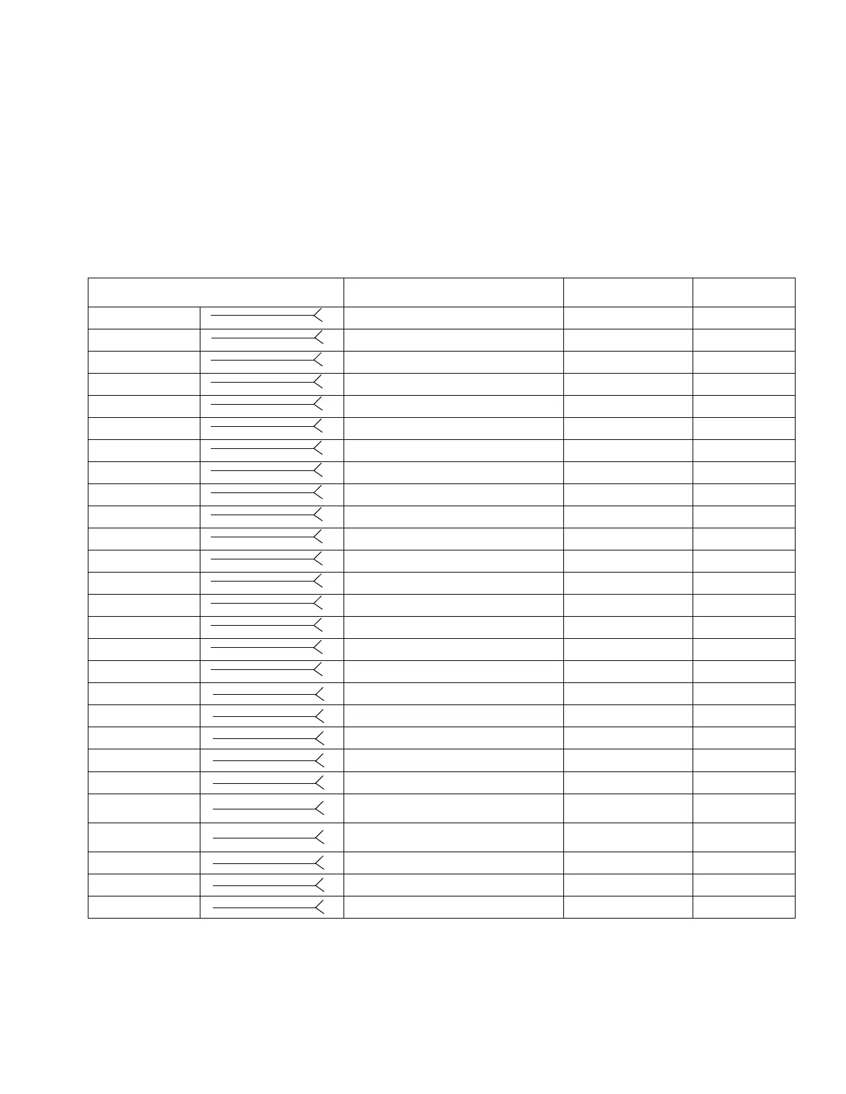
The cable length of interface cable assembly 123793 is 50 ft (15.2 m). The following table identifies the cable
interface signals.
NOTE: See Appendix D - I/O Signal Descriptions, page 146, for I/O signal descriptions.
Swirl-related inputs apply only to systems with Swirl Dispensers.
* Dispense Error may be active high or low, depending on the setting on the Gateway setup screen. See Discrete
Gateway (Automation) Setup Screen, page 109.
Wire Color Description Pin Type
D-Sub
Pin No.
Green/Yellow Isolated Logic Power Supply Supply 51 and 27
Gray Isolated Logic GND Supply 70
Blue/Green Dispense Ready Digital Output 9
Brown/Green Dispense Error* Digital Output 11
Blue/Orange Dispense In Process Digital Output 12
White Dispense Purge Digital Output 15
Blue Dispense Remote Start Digital Output 16
White/Yellow Style Bit 1 Digital Input 52
Blue/Yellow Style Bit 2 Digital Input 53
Brown/Yellow Style Bit 3 Digital Input 54
Black/Red Style Bit 4 Digital Input 55
White/Red Style Strobe Digital Input 56
Blue/Red Dispense Complete Digital Input 57
Brown/Red Error Reset Digital Input 58
Black Remote Start/Purge Digital Input 59
Black/Gray Dispense Valve 1 Digital Input 73
Brown/Orange Dispense Valve 2 Digital Input 74
Brown Command Value Analog Input 1
Black/Yellow Analog GND Analog Input 2
White/Gray --- 3
Blue/Gray Swirl 1 Speed Command Analog Input 21
Brown/Gray Swirl 2 Speed Command Analog Input 23
White/Orange
Dispense Valve 3/
Swirl 1 Enable
Digital Input 75
Black/Orange
Dispense Valve 4/
Swirl 2 Enable
Digital Input 76
Black/Green Digital CMD 1 Digital Input 77
White/Green Digital CMD 2 Digital Input 78
Orange --- N/C