On-Board Polyethylene Feed Systems
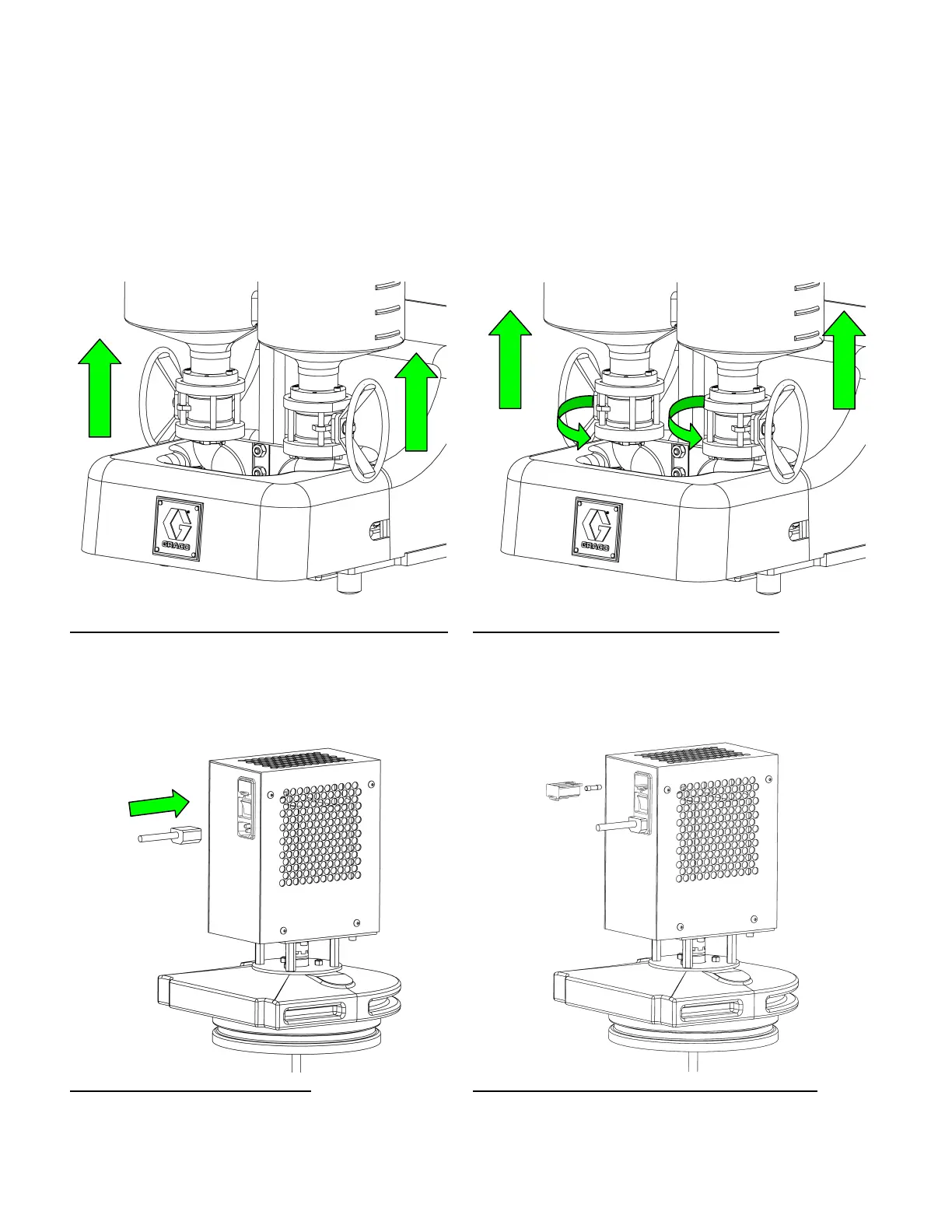
14. If necessary, to remove tanks from pump housing,
remove the two top screws holding the tank to
upright support and remove the six (6) socket head
cap screws that hold the tank to the ball valve
assembly and lift the tanks off.
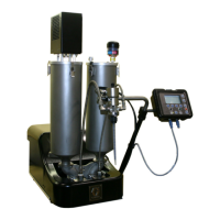
15. If necessary, to remove tank and ball valve
assembly from pump housing, remove the two top
screws holding the tank to upright support and
loosen (Note: There is no need to completely
remove) the six (6) socket head cap screws that
hold the tank to the pump housing and rotate the
ball valve assemblies counter clockwise and lift the
tanks off
Figure 9: Tank Removal From Ball Valve Assembly
Figure 10: Ball Valve Assembly Removal
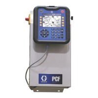
16. Agitator assemblies require their own outlet and
power cable which will be provided with the unit.
Simply plug the appropriate in to a 120V/60Hz
Outlet and turn the power switch on.
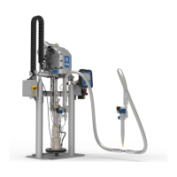
17. If necessary, the fuse can be replaced by sliding
open the fuse drawer, removing the existing fuse
and replacing with the new one.
Figure 11: Final Clamp Position Figure 12: Tank Removal From Pump Housing
312394B 11 of 71