On-Board Stainless Steel Feed Systems
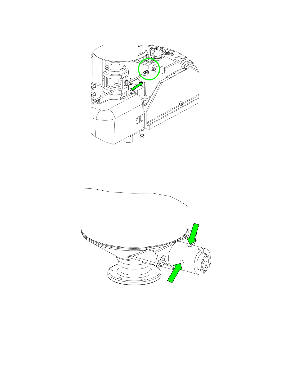
4. Insert the harness into the plug provided as shown in the figure below. Refer to main manual 312393 for
instructions on interfacing the sensors to the HMI
Figure 37: Low Level Sensor Harness Installation
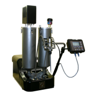
5. Once the sensor is installed mechanically, it can be calibrated to the material you are using by locating the
adjustment screw on the sensor. It should be visible though one of the four holes in the sensor well (see figure
below.) If it can’t be seen, loosen the retainer nut and turn the sensor until it can be seen then retighten the nut.
Figure 38: Proximity Sensor Adjustment Locations
6. The most accurate way to calibrate the sensor is to fill up the tank just past the sensor and make sure the
yellow LED is lit on the sensor itself. At this time you can also verify that the HMI is reading material in the tank
7. Next, drop the level of fluid in the tank past the sensor and make sure the yellow LED light is off. If the light
does not go off, it is picking up material that is stuck to the well. Adjust the sensor until the light goes off and the
sensor should now be calibrated and ready to go.
312394B 32 of 71