Troubleshooting
4.Checkfunctionalityofthedirectionalvalve(207).
a.Conrmthatthedirectionalvalvecable
isconnectedproperlyfromHCMport15
tothedirectionalvalvebody(207)and
isnotdamaged.Inspectwiringinside
thecoverofthedirectionalvalve.See
ElectricalSchematics,page102.
b.Duringoperation,thedirectionindicatorlights
onthedirectionalvalvebody(207)should
switchonbasedonthevalvethatisopen.
c.Turnonthemotorandstallthepumpsatthe
lowestpressuresetting(compensatorknob
turnedfullycounter-clockwise).Thepump
willtravelineithertheAorBdirectionuntil
thepressuresettingisreached.
d.Identifythesolenoidthatisoperatingby
viewingthedirectionindicatorlightsonthe
coverofthedirectionalvalve(207).Measure
voltageacrosstheassociatedterminalsto
determineifpropervoltageisreachingthe
valve(approximately200to240VAC).See
ElectricalSchematics,page102,andthe
tablebelow,toidentifytheproperterminals
tomeasureacross.
e.Triggereachproximityswitch(211)with
theshaftofascrewdriver,conrmingeach
solenoidwithinthedirectionalvalve(207)
operatesasdescribedintablebelow.
f.Ifoneorbothsidesarenotoperating
properly,accordingtothetable,rst
reconrmwiringtodirectionalvalve(207)
perElectricalSchematics,page102,then
replacedirectionalvalve(207).
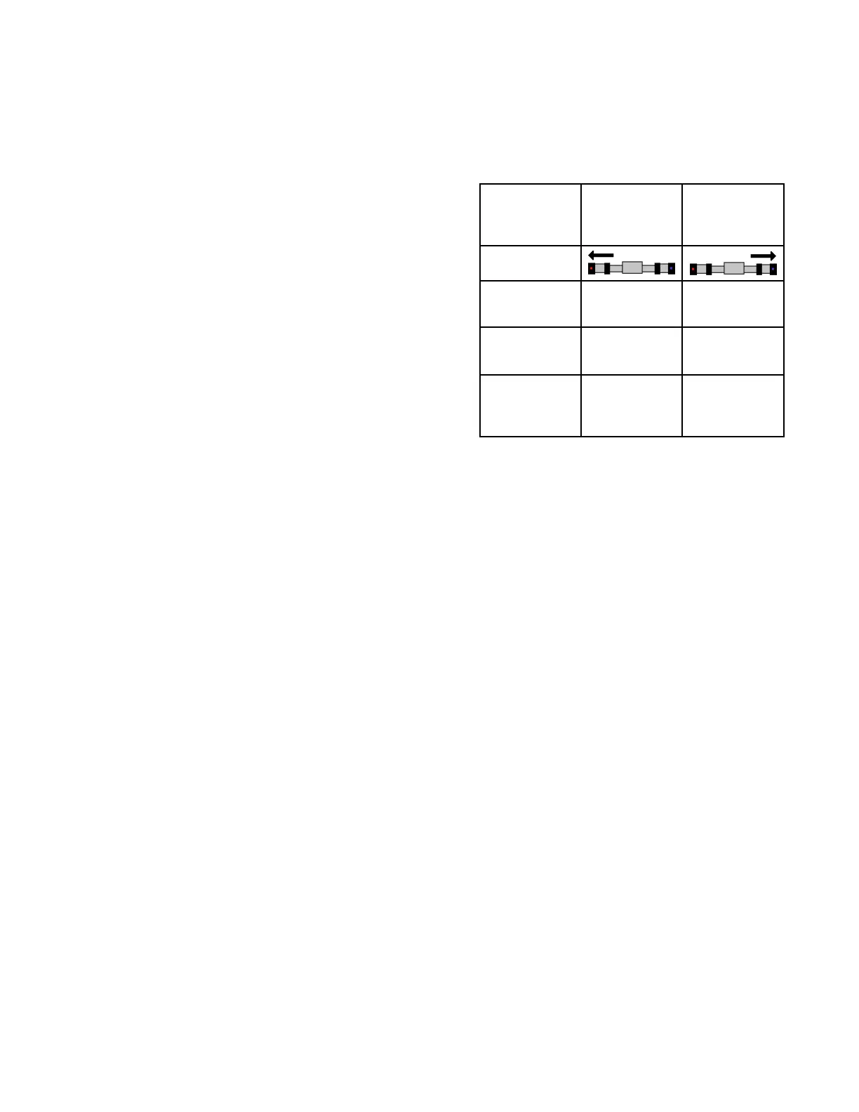
For For
For
given given
given
pump pump
pump
movement movement
movement
direction: direction:
direction:
Pump Pump
Pump
driving driving
driving
left left
left
(toward (toward
(toward
park park
park
position) position)
position)
Pump Pump
Pump
driving driving
driving
right right
right
(away (away
(away
from from
from
park park
park
position) position)
position)
ADMindicates
Indicatorlight
ondirectional
valvecover
Leftarrow,
labeled“b”
Rightarrow,
labeled“a”
Lastproximity
switch
triggered
Rightside
proximity
switch
Leftside
proximity
switch
Terminalsin
directional
valve
energized
Terminals
associated
withredand
orangewires
Terminals
associated
withblackand
whitewires
NOTE: NOTE:
NOTE:
Fordiagnosticpurposes,itispossibleto
manuallyoverridethedirectionalvalvebyusing
asmallscrewdrivertodepressthebuttonin
thecenterofeitherdirectionalvalveendcap.
Depressingthebuttonintherightendcapshould
causethepumptotraveltotheright.Depressing
theleftbuttonshouldcausethepumptotravel
totheleft.
5.Ifyouhavedeterminedthatthecauseisnone
ofthepreviouspossiblecauses,checkfora
loosepistonpackingretainingbolt.Thiscauses
thepistontocontacttheinnerfaceofthepump
inletangebeforetheswitchingplateactivates
theproximityswitch.Shutdowntheunitand
disassembletheappropriatepumpforrepair.
Following Following
Following
step step
step
1, 1,
1,
if if
if
the the
the
proximity proximity
proximity
switch switch
switch
indicating indicating
indicating
lights lights
lights
do do
do
not not
not
light: light:
light:
6.Checkforlooseorfaultyproximityswitchcable
orconnections.Conrmtheconnectionstothe
proximityswitchesaretightandinternallyfree
fromoilandothercontaminates.
7.Swapthecablestotheproximityswitchestosee
iftheproblemfollowstheswitchorisinthecable.
Replaceeitherthefailedswitchorthecable.
8.ReplacetheHCM.SeeReplaceHCM,page70.
334946H
41

 Loading...


